
Phantom 2.0
Introducing Phantom 2.0, our robot for the 2021 competition, in its “final” form!
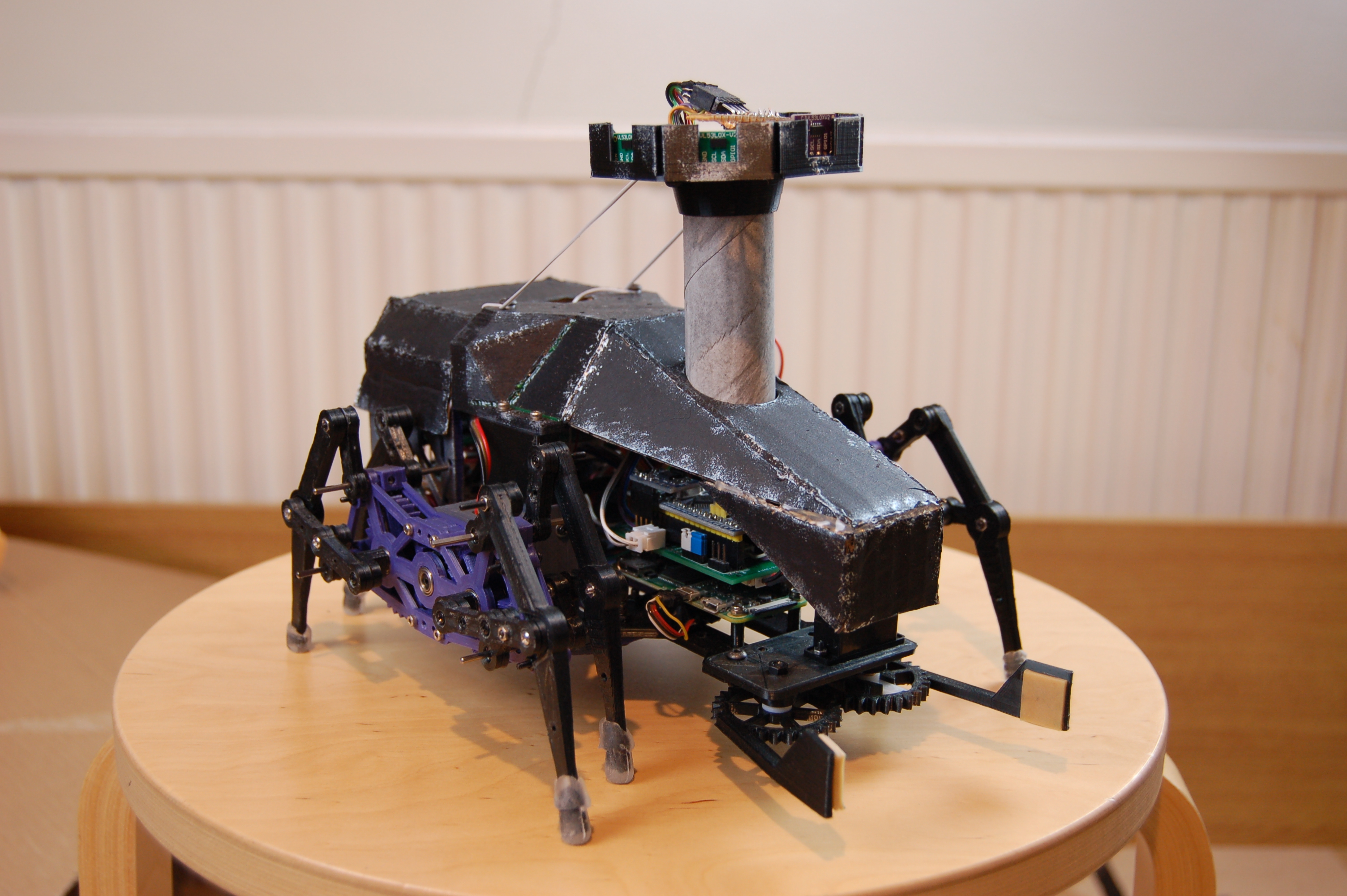
The main structure follows the same layout as Phantom 1 from 2019, but it’s much stronger – and more finished.

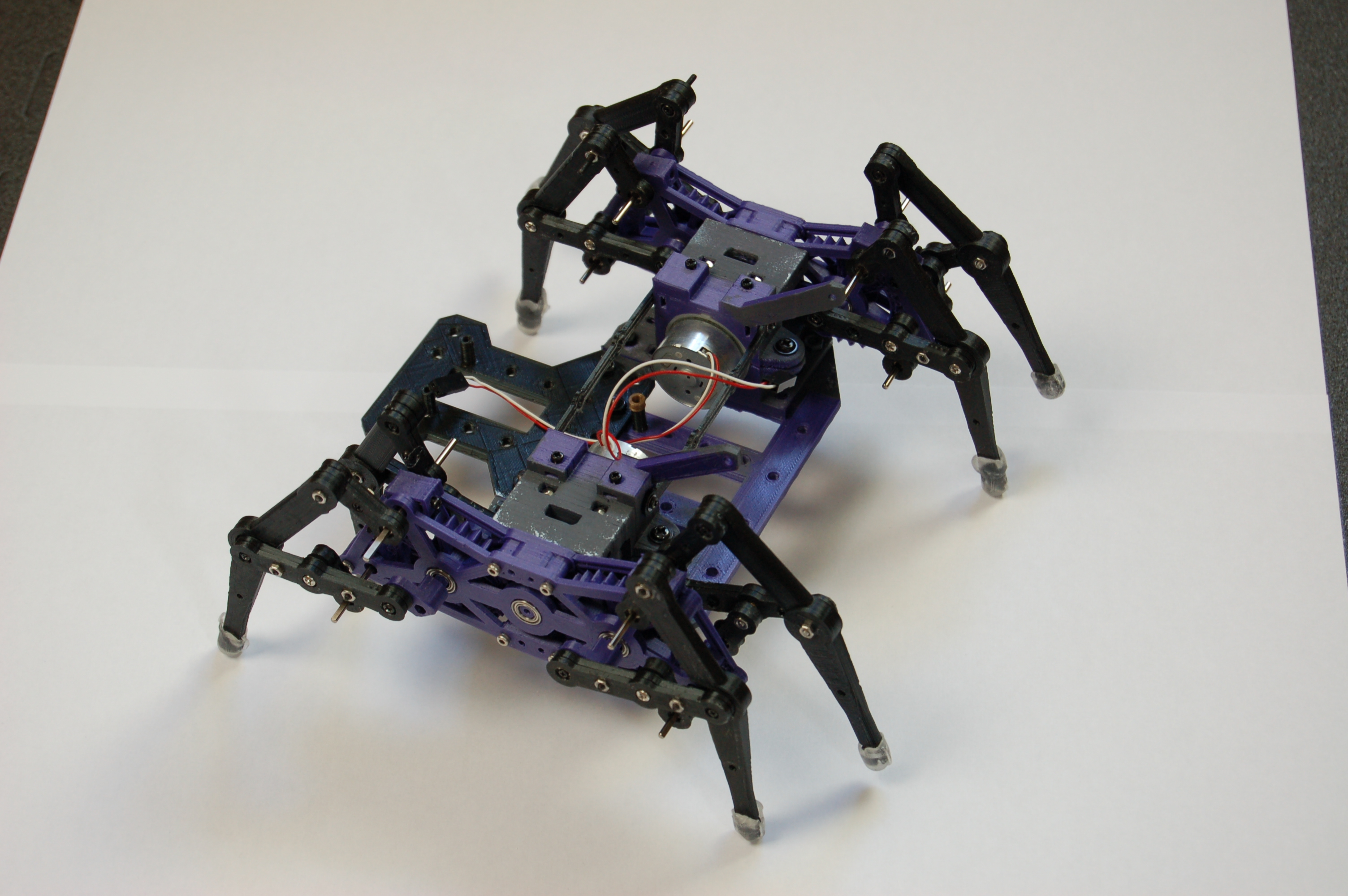
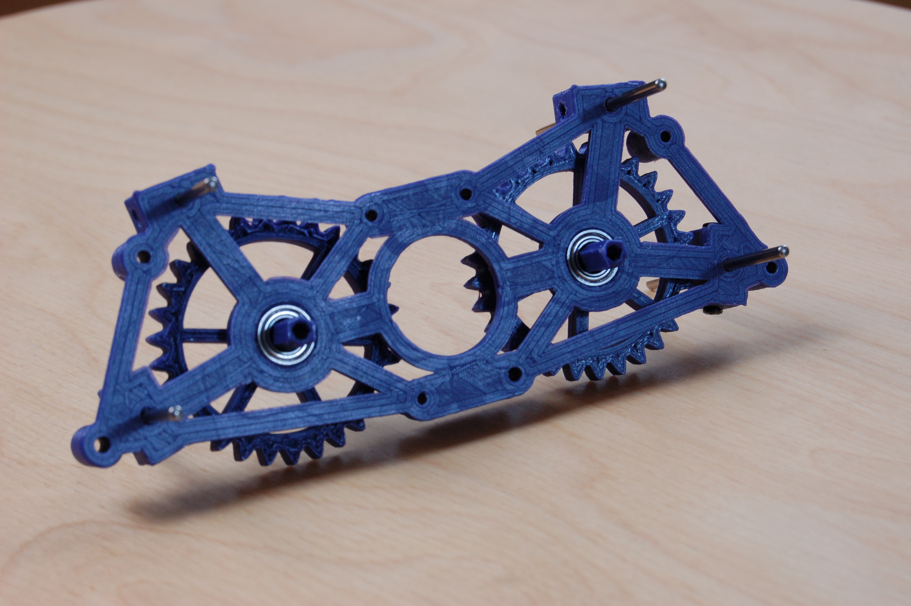
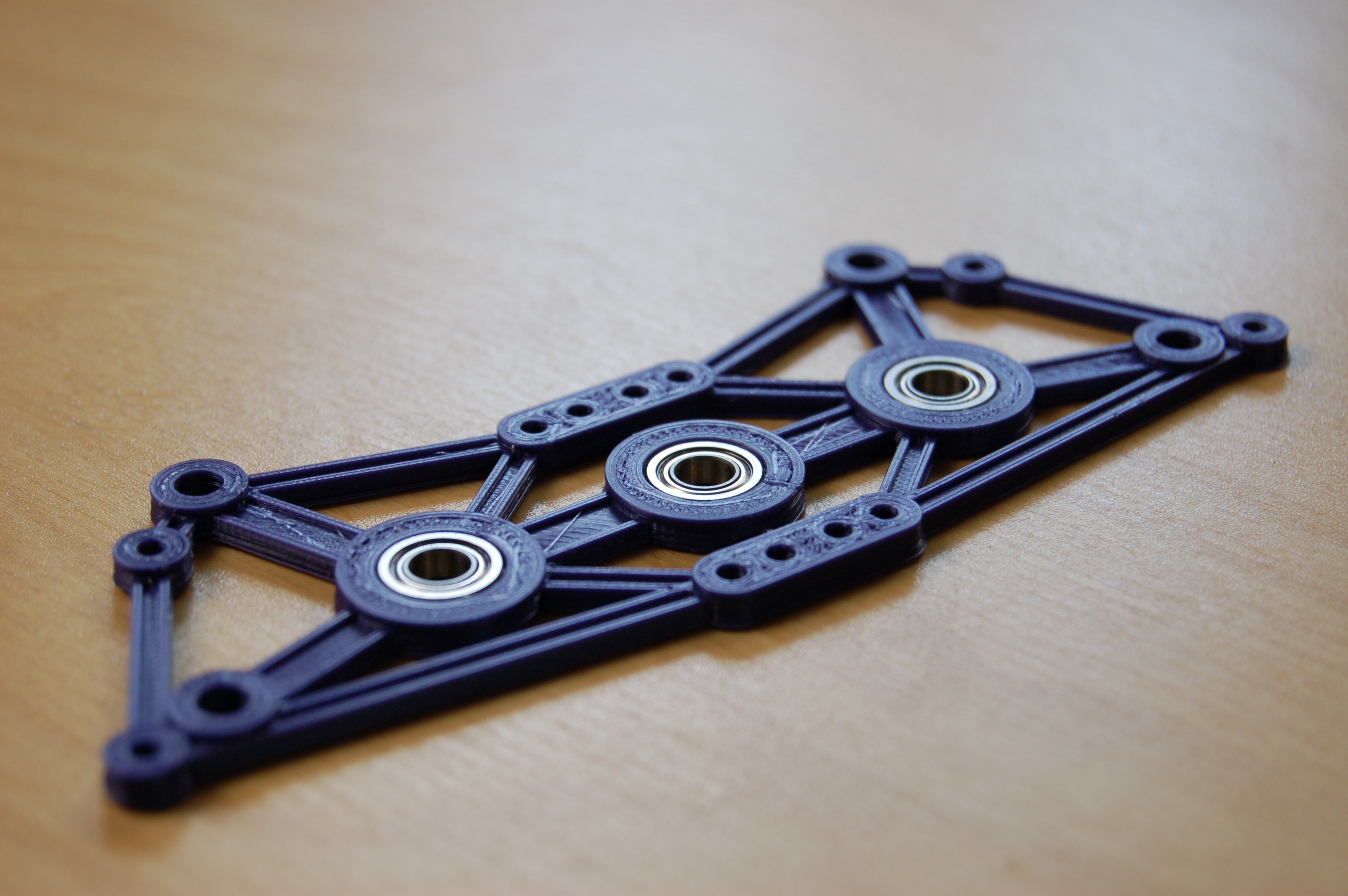
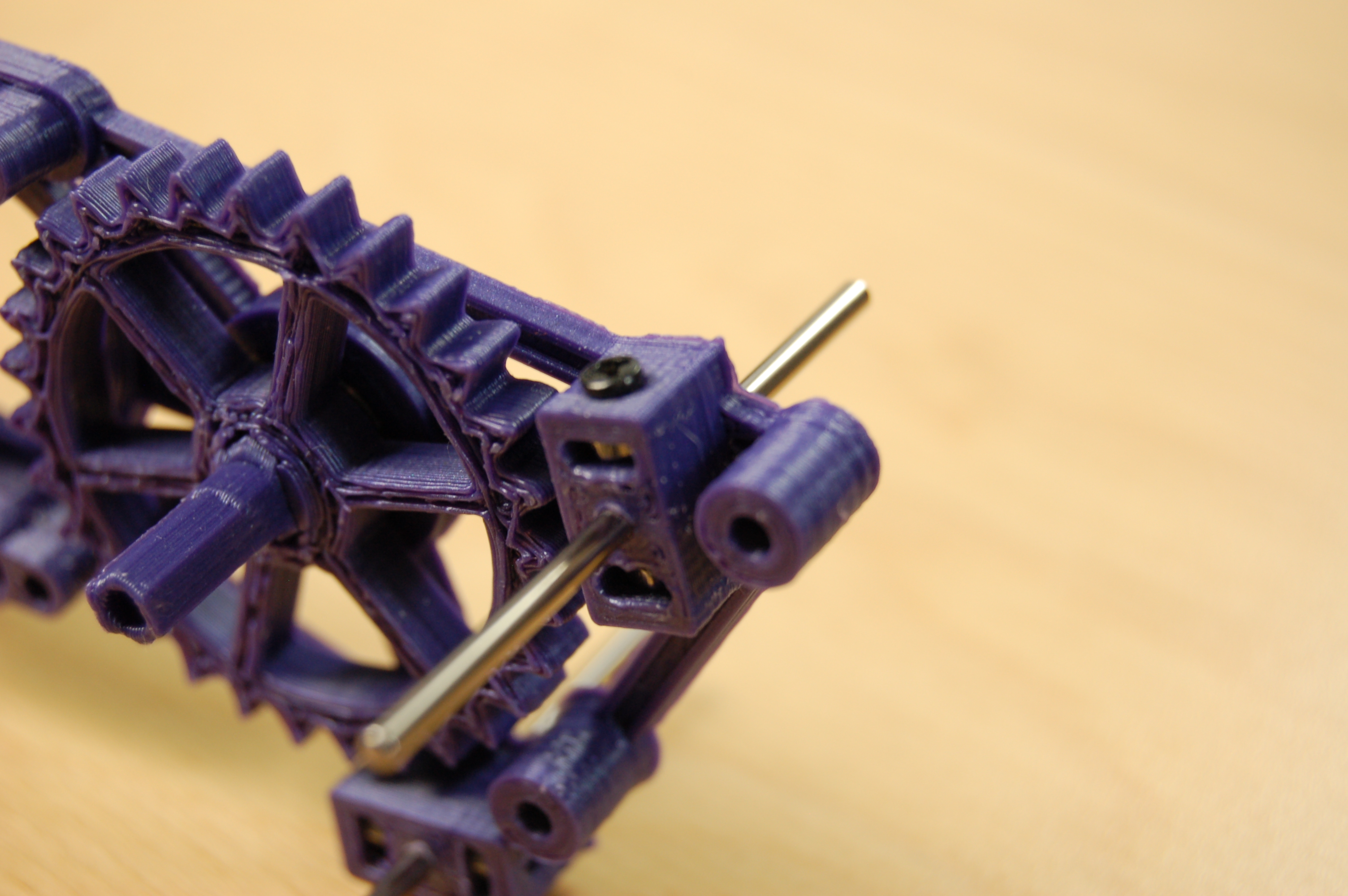
The critical part that went through many iterations is the gearbox / leg mechanism. All the joints have mini ball bearings now and they connect to the gearbox with metal axles, so everything is much less wobbly and much stronger than before. (The proof of that is Phantom 2.0 went through all the challenges without any mechanical issues! No lost screws, disconnected joints or broken parts at all – which is unusual!)
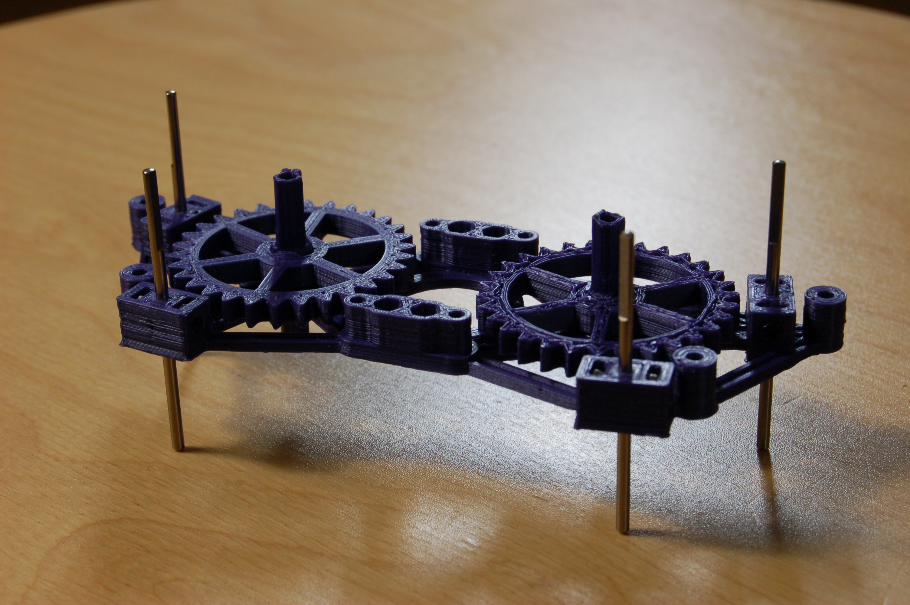
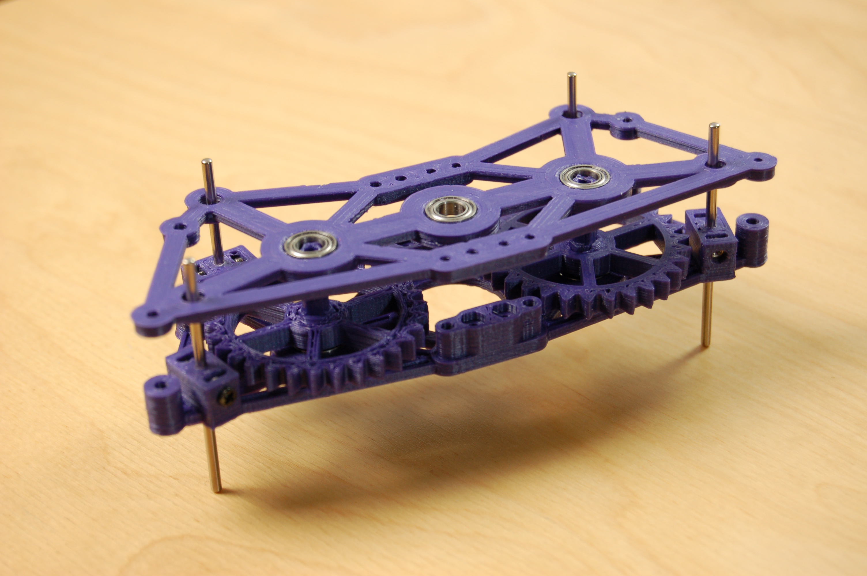
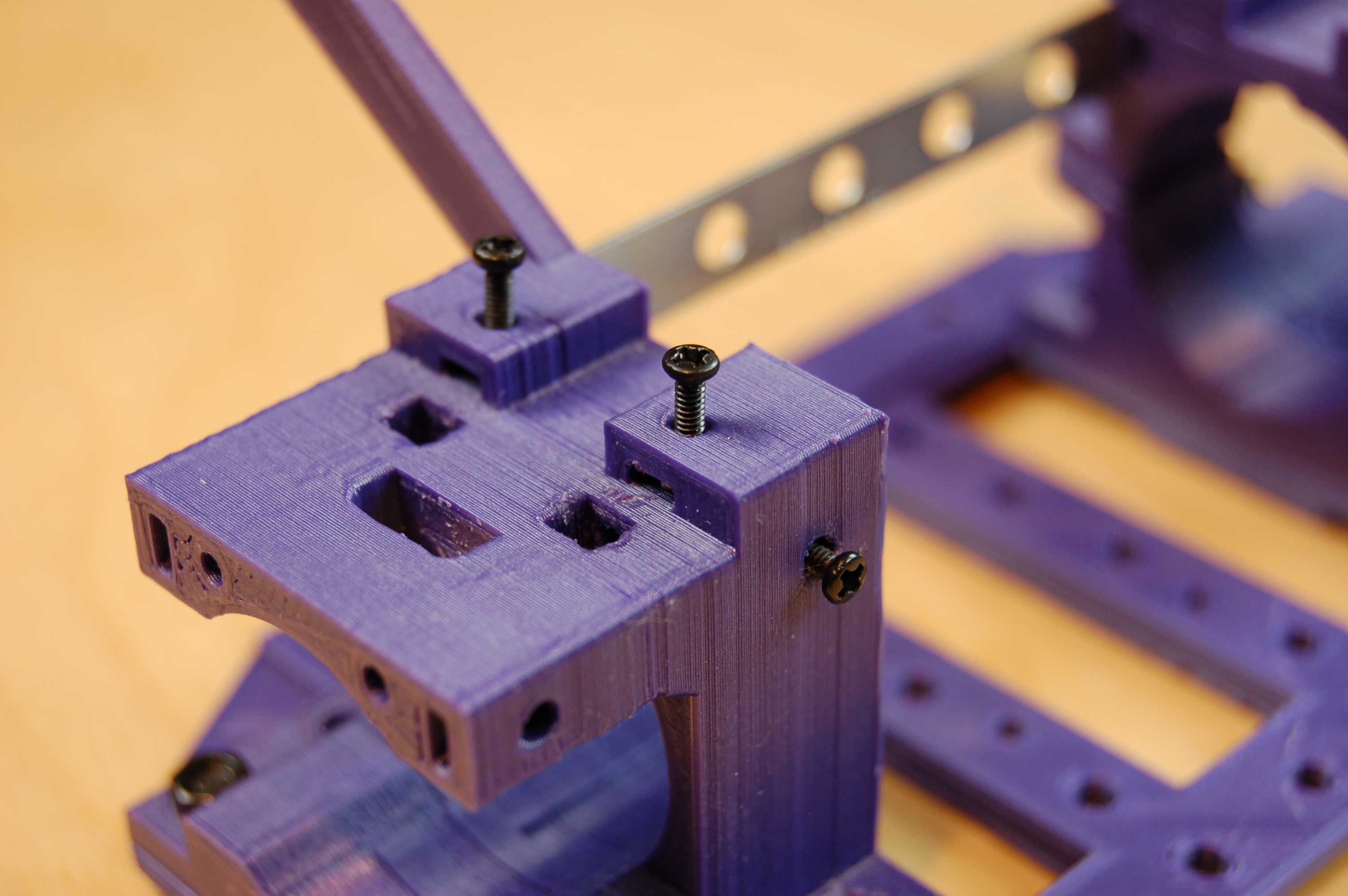
Making sure everything is straight and connects to everything else within fine tolerances – but also not too rigid! – wasn’t easy. 3D printed parts, when assembled together, will never fit perfectly. (Either because the printer isn’t tuned perfectly or print settings are not 100% ideal or different plastic parts expand or shrink in slightly different ways…)
Mixing 3D printed and metal parts is not trivial, but perhaps can bring the best of two worlds. Using screws to tighten and adjust connections and captive nuts (nuts that can be slotted in so that they are held in place within the plastic part) work great.
And although we didn’t make a completely closed shell, we have very stylish cover pieces.
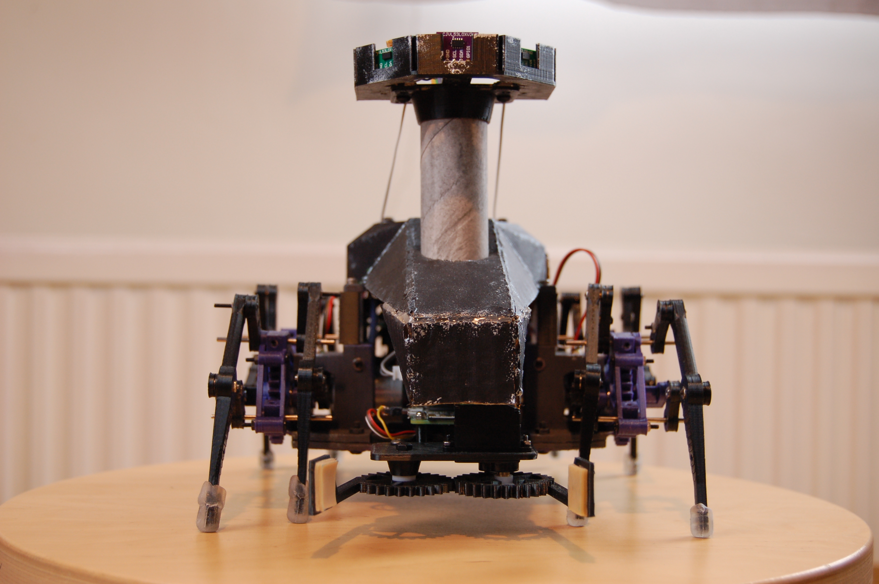
The 3D-printed section of the cover had an interesting shape based on some of the NASA Mars rovers. This was built on using cardboard. The structure is surprisingly strong, given how weak the material is by itself. The cardboard section follows the angular design of the original piece, with a hole in the front for the mast to go (also inspired by the Mars rovers).
For painting, we wanted it to look like the robot was alien in design. The legs already added to this, so the cover was painted black and grey. On top of this, it had to look like it was old, and had been working for a long time, so we used a piece of sponge and silver paint to make it look like the black paint had chipped off, revealing the metal underneath.
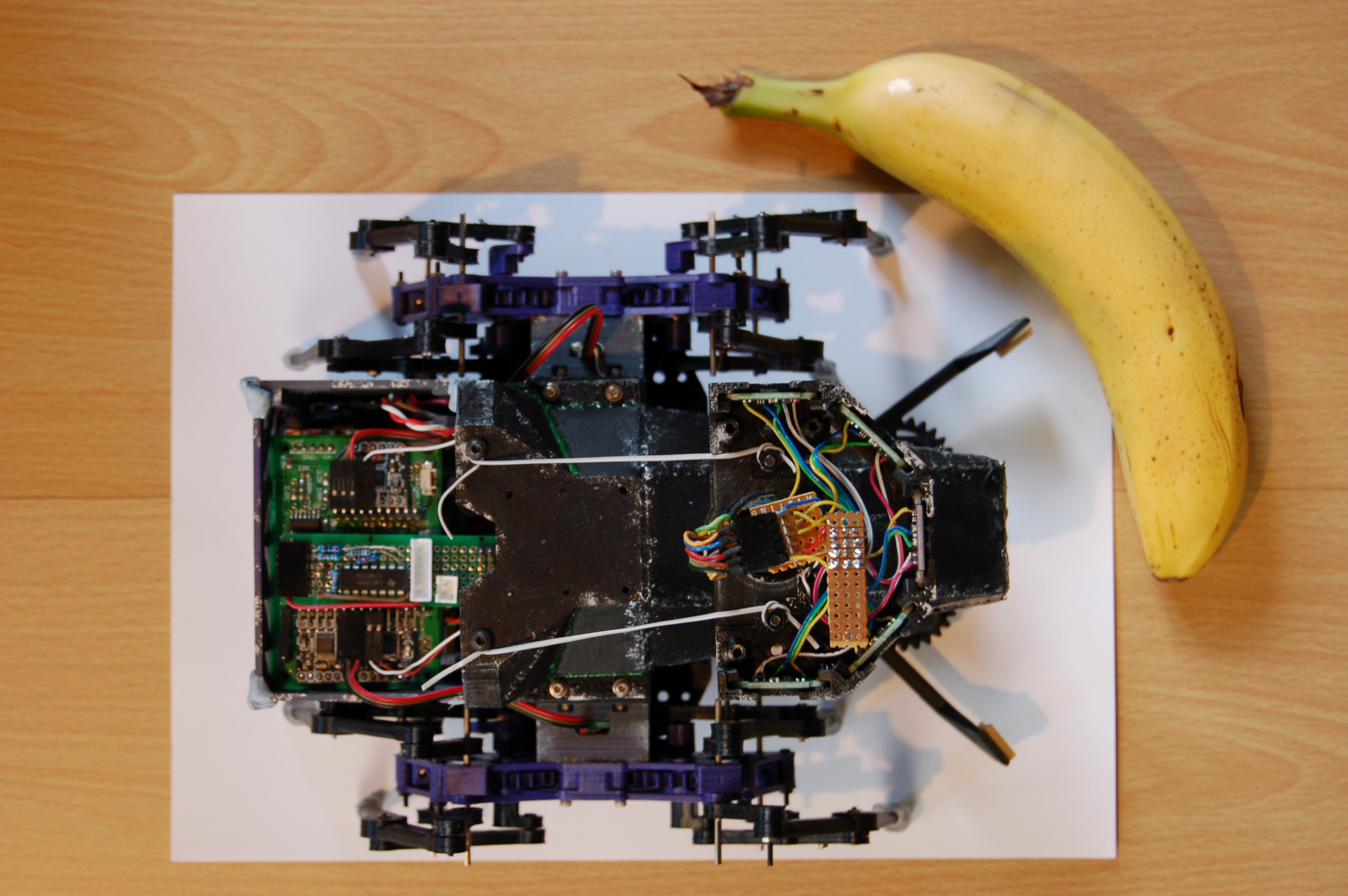
Main Components
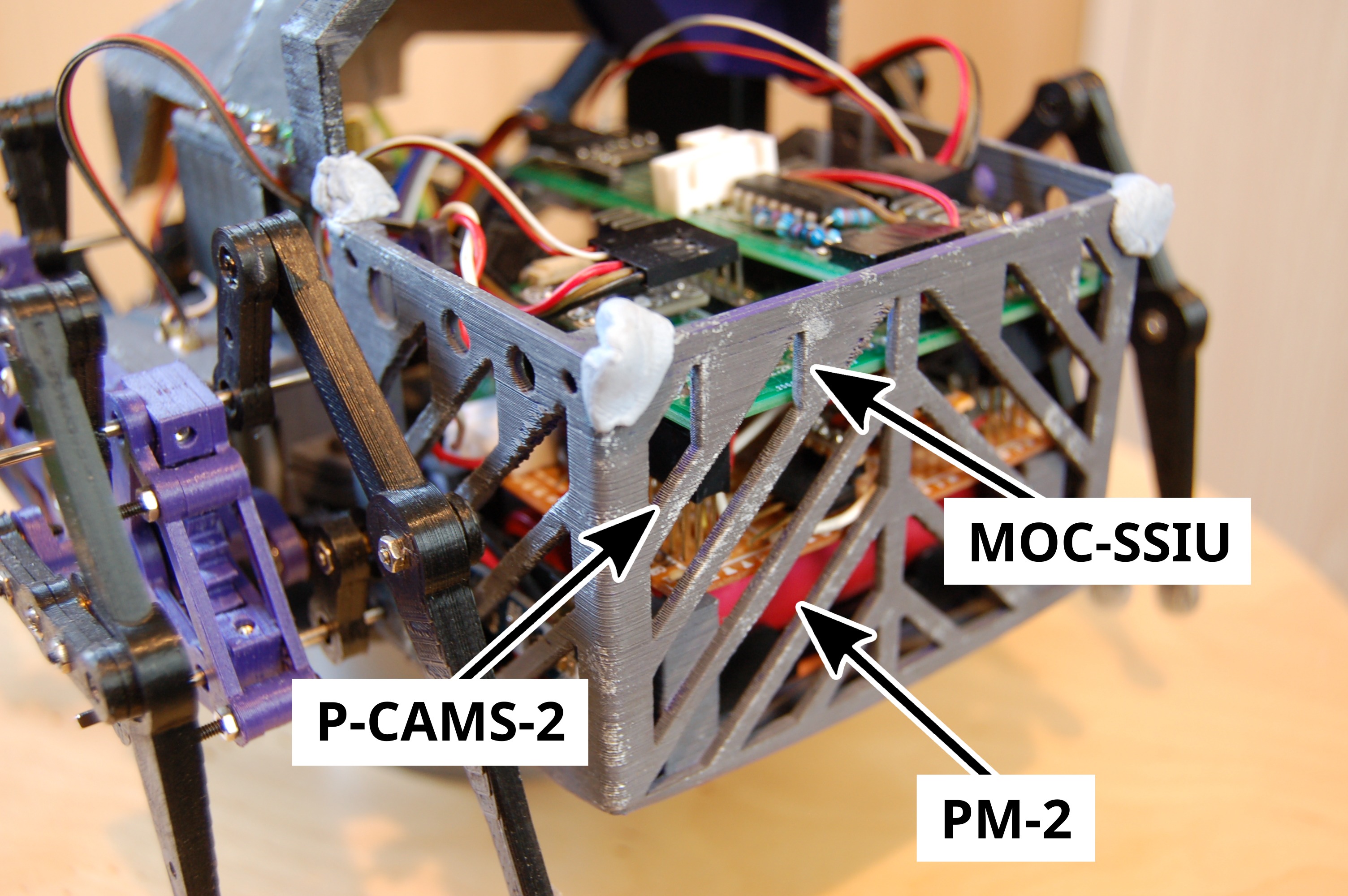
As for the insides, here is a complicated diagram, trying to show everything:
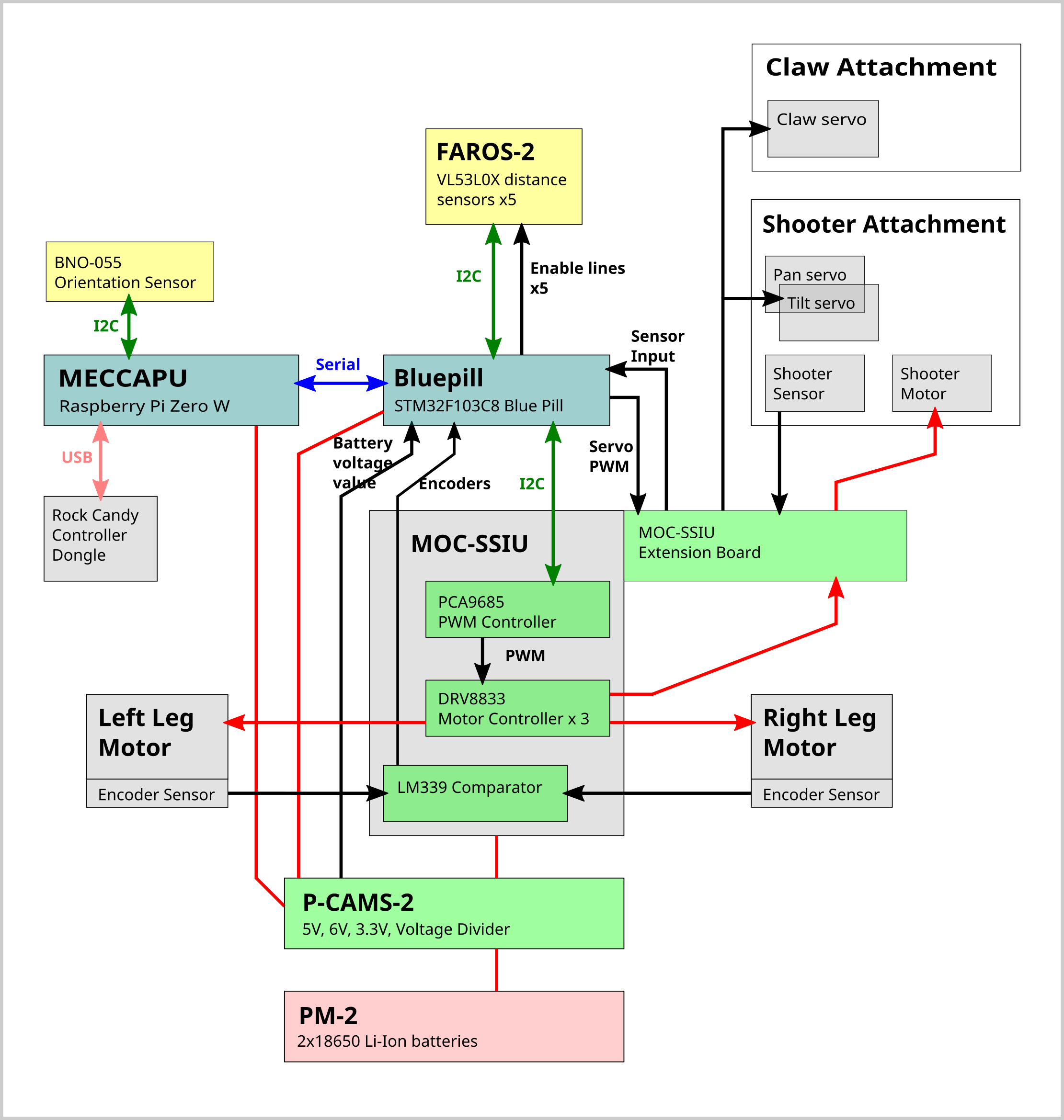
At the back:
PM-2 and P-CAMS-2: Batteries and DC converters to provide various voltages to components (originally created for Phantom 1 in 2019).
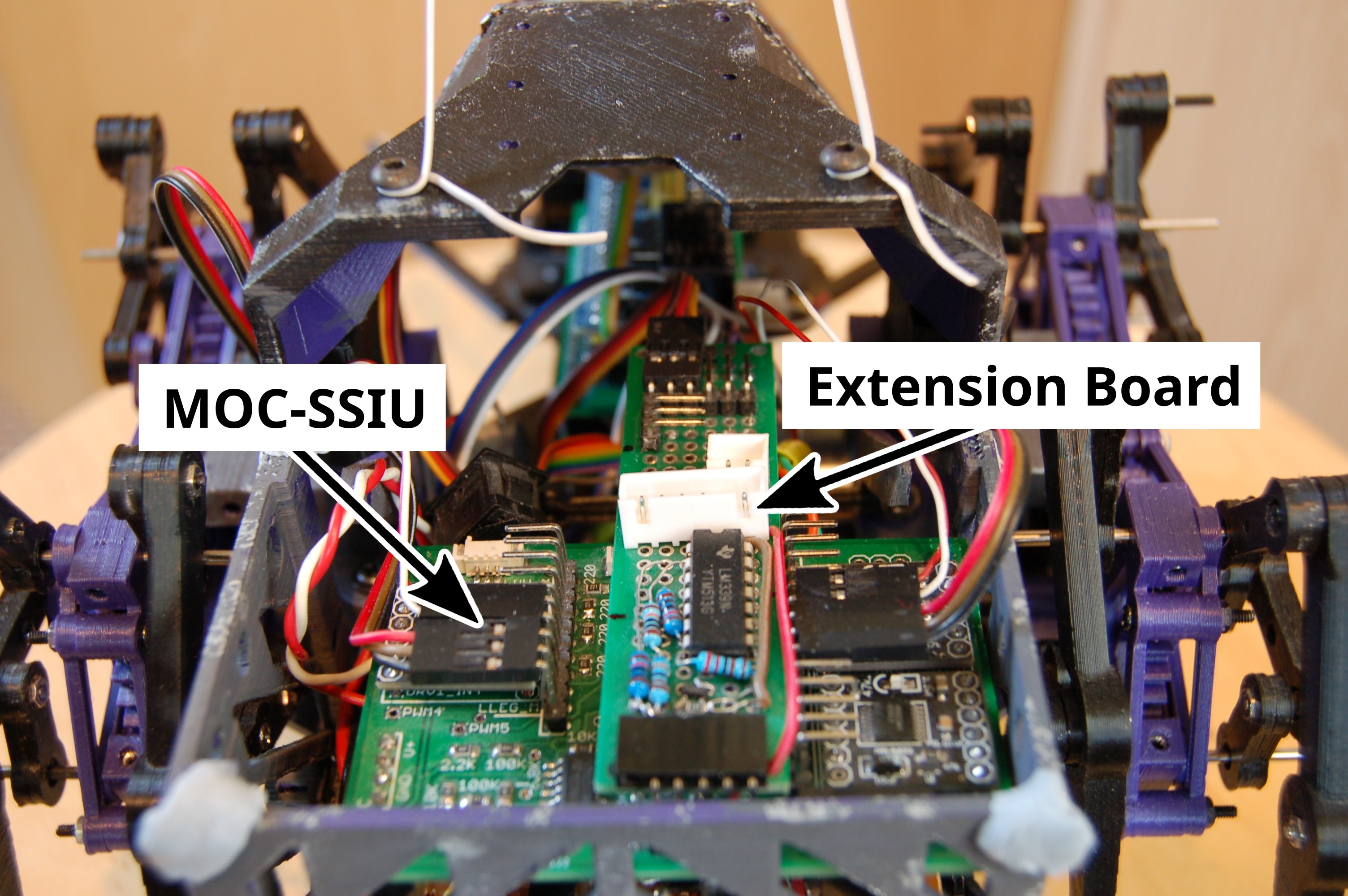
MOC-SSIU – the MOtor Control and Speed Signal Integrator Unit: includes a PWM controller, motor drivers and some signal filtering for motor encoders (also from last year).
MOC-SSIU Extension Board: a late addition to support the shooter and claw attachments (mainly to route connections between components).
At the front:
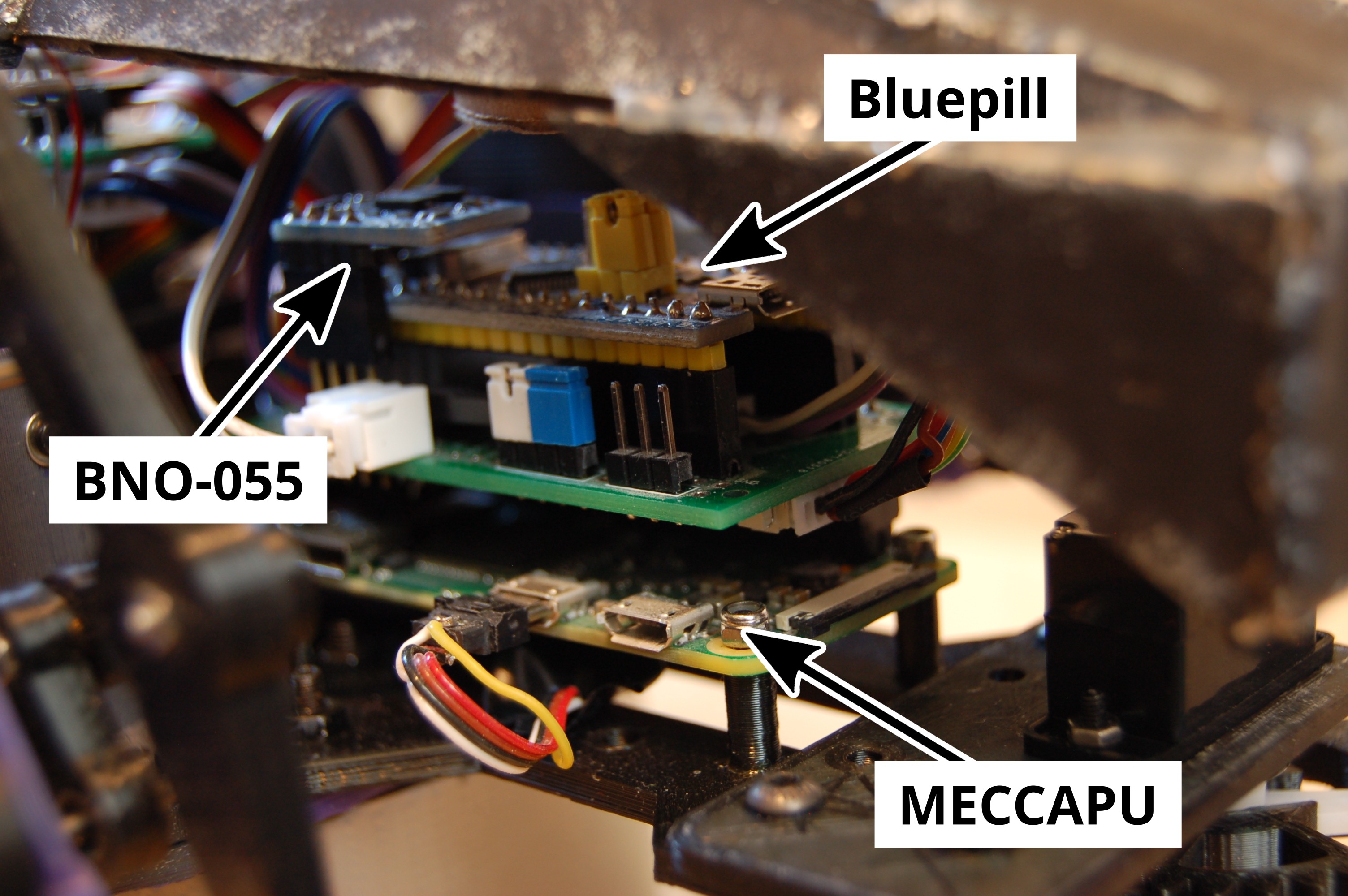
MECCAPU – Mars Exploration Central Computing And Processing Unit: a Raspberry Pi Zero W, inherited from our 2019 robot, responsible for all high level control. It’s connected to three other components: the BNO-055 sensor (via I2C), the dongle for the Rock Candy controller and, most importantly, to the Bluepill board via serial.
Bluepill: an STM32F103C8 microcontroller board (the popular “Blue Pill”): interfaces with sensors and actuators, deals with all the the low-level, real-time tasks (e.g. controlling motor speeds with a PID loop). It communicates with MECCAPU via a serial interface: can accept simple commands, like setting motor speeds and continuously reports distance measurements and other data.
BNO-055 Orientation Sensor: used as a compass to get absolute direction (but using the BNO-055’s default sensor fusion).
FAROS-2: new version of our distance sensor array: contains five VL53L0X sensors in a half-circle. Can be mounted either at the top of a mast (to give it clear view of arena walls in all directions) or lower, at the front (when the shooter attachment is mounted at the top instead – in this case the two side-facing sensors are blocked by legs).

Motors and attachments:
Leg Motors: the legs are driven by two DC gear motors and DRV8833 motor drivers (on MOC-SSIU). They have simple optical encoders to control speed.
Shooter Attachment: consists of two servos, a shooter DC motor and a sensor to detect the position of shooting mechanis’s pinion gear (mounted at the top of the robot). See all the details in the previous post.
Claw attachment: a simple claw driven by a single servo, to grab boxes (mounted at the front).
And finally, some test driving footage: