
M.E.T. – Part III
In 2018 we had a crazy idea: we decided to compete at Pi Wars for the first time, as Mars Exploration Team, and built our first robot, modelled after the Mars rovers, with four individually powered and steerable wheels. It was a fairly complicated design for a first experiment. It mostly worked, but it was somewhat unfinished, and we failed at most of the challenges.
In 2019 we had a new crazy idea. We changed our name to Mars Extraterrestrials, started experimenting with alien technology, and built a new robot, a strange spider-like walker. Some of its components were improved versions of what we had before, but the design was completely new, with new problems, especially the mechanical parts. It mostly worked, but it was mostly unfinished, and we failed at almost all of the challenges.
For 2020 we have another crazy idea. It’s so radically different, so outside-the-box, so completely new, that for the first time, we are slightly worried: we have decided not to start with a new design this time, but to improve and finish the previous one! Start with what we have already! Fix all the problems! Gradual improvements! Thorough testing! Learn from previous mistakes! Make it reliable! For the first time, we are trying to do something sensible!


So for 2020…
After two failed (destroyed by Martians) attempts at exploring the Red Planet (and millions of pounds clogging the drains), we have launched our business strategy mark 2.A2Z part 2B. (This name was invented after three meetings of heated debating on the best snack and then realising at the last minute we were supposed to be working.) Further info: everything in the name can be ignored – it’s all just so that we look like we are doing something.
The strategy is informally known as M.E.T. – Martian Emergency Team (because Mars Exploration Team and Mars Extraterrestrials wasn’t enough confusion). We are now officially in charge of Health & Safety on Mars. The fact that there isn’t actually anyone on Mars makes our job significantly easier and basically means we don’t have to actually do anything. Also, just to clarify, accidents in: orbit, crashes, and as a result of jumping too high are not our problem because they didn’t actually happen on the planet (you still have to pay us though: snacks aren’t free you know).
All in all, this shouldn’t fail too catastrophically… Always remember to wash your hands, clean your spacesuit, and stay safe!
Phantom 2.0
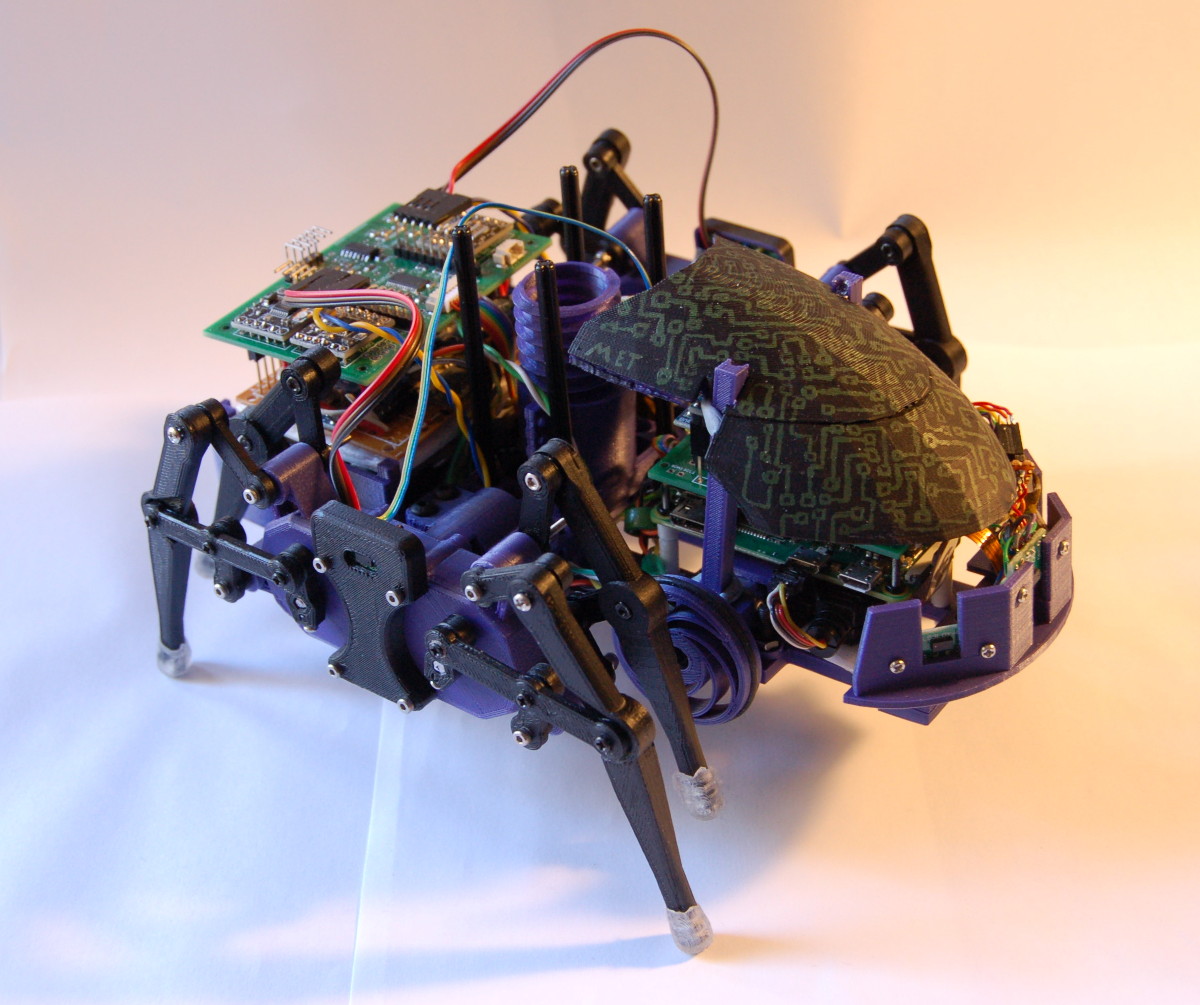
We have decided to keep our design from 2019. We will improve (or rather finish properly) our spider-like walker robot, Phantom, and repurpose it to assist in various emergencies (obviously including common tasks, such as shooting down zombies).
After the 2019 competition we reviewed what happened at each event. We did a detailed analysis of what worked and what didn’t (mostly the latter) and identified what needs to be fixed and how.
As a result, here are our plans for Phantom 2.0. (It will be very interesting to look at this again in a few months and compare it with the actual end result!)
Leg mechanism
We will keep the previous idea, using the Klann linkage, to drive 2x4 legs with a pair of motors, using differential steering. We still believe this is a valid concept (beyond just the cool “spider” look) and can be made efficient and reliable.
Planned improvements:
-
Reduce the number of screws and use more ball bearings: In our previous design the plastic parts of the joints were quite small and not printed precisely enough. The joints were connected by screws and lock nuts, and each had to be tightened “just right” manually. This was really difficult to do reliably. (If even one joint is too loose, the legs will wobble a lot, or if it’s too tight, they will get stuck easily.) Switching to ball bearings for joints should ensure smooth movement and reduce wobble.
-
Redesign the gear box: The previous gearboxes have two metal axles, with a gear in the middle. Outside the gearbox, on each side, small plastic cranks connect the leg joints to the axles. This worked mostly OK, but the axles were wobbling a little and the cranks were a bit fragile and required yet more screws, so overall, this design has probably too many parts that are difficult to assemble reliably. We have an idea about simplifying all this, to reduce the number of parts and hopefully make it more stable.
-
Make sure the gear box and the motor holder have no weak points like the one that snapped last time in Pi Noon.
-
Experiment with changing the gait, maybe make the legs slightly longer to reduce the risk of getting stuck on uneven terrain.
Motors
We had a serious issue with fine speed control: the big motors we chose originally were very hard to control precisely at low speeds and the much smaller motors we switched to at the last minute were just both too slow and weak.
We will try to use the original motors again, but with a different gear ratio and will try and find the right speed/torque balance. We will keep the existing sensors to measure RPM and the PID speed control logic, as these have proven to be reliable and helped a lot to understand our speed control problem.
The motor controllers and PWM controller we used before worked really well, so they will stay. We will try to further improve the custom PCB and reduce the number of internal connections.
Power
The 2x18650 Li-ion batteries and the DC converters we chose (a small 5V buck converter for the electronics and a big 6V one for motors) worked well. The addition of very basic voltage monitoring was also worth it (less worries about when to recharge batteries between challenges).
We are planning to run the main motors off the batteries directly this time (relying on PWM not to overload them), and use a smaller 6V DC converter only for servos, to reduce size and weight. We will also try to make a “proper” PCB for all this, and maybe add a circuit to be able to power off programmatically.
Body
Phantom’s main structural parts are all 3D-printed:
- the chassis: a fairly simple “base plate” with lots of mounting holes to attach the leg assemblies with the motors, the stacked PCBs for the Pi and the microcontroller, etc.,
- a front section, housing the camera and three of the ToF sensors,
- a “box” at the rear for the batteries with the power and motor control boards stacked on top,
- the two leg assemblies (or gear boxes) with the motors,
- an outer shell to nicely cover everything.
We will keep this design, although some of it will need to be resized or changed slightly – it’s all designed in OpenSCAD and parameterised, so changes are relatively easy. We will definitely need to change/add the following:
- finish the outer shell to properly cover and protect(!) the whole body,
- add an optional high mounting attachment for the camera and the ToF sensors,
- add another optional attachment on the top for the shooter platform.
Raspberry Pi and microcontroller
We will keep our “proven” architecture:
- Pi Zero W for high level control (small, low-power, cheap, versatile and should have plenty of processing power for what we need)
- STM32F103 microcontroller (“blue pill” board), connected to the Pi via serial, controlling all the hardware, responsible for the low-level, real-time tasks (cheap, powerful enough to drive everything, has lots of I/O)
ToF distance sensors
Previously we were using five ToF sensors for distance measurements (facing front, left-right and 45 degrees each side), run by the microcontroller. These have proven to be very reliable, but we have a problem with latency: it’s due to a limitation in the driver and/or the way we handle the communication between sensors, microcontroller and the Pi. We have already identified how to improve the driver code to allow interleaving measurements from multiple sensors: this will definitely speed things up. We need to investigate this further to check if we have any more bottlenecks.
Another idea is to add more sensors: if latency can be reduced, this should be easy – and with more sensors, we’d get more resolution to see the world around the robot, which could be used to maintain a simple map of the environment, or at least to identify walls/corners/openings in a maze.
9-DOF orientation sensor
We will keep using the BNO055 module as before, probably only as a compass to get absolute orientation. Previously we have only used it in the Hubble Nebula challenge, but it will come useful for the maze and maybe in other situations as well, if we manage to do some sort of more clever mapping and planning than before. We are considering an optional attachment to mount these sensors high, to be able to look around better in some of the challenges (see below).
Camera
We will use our existing Pi camera. It’s a wide-angle lens version, which could come very useful in some of the new challenges.
We are planning to mount the camera very high (maybe with an optional attachment) this time, so that we can get a better view of the area in front of the robot, for Eco-Disaster and Minesweeper.
Although last time we weren’t quite ready to complete the Hubble Nebula challenge, our OpenCV-related software was almost ready, including a separate application for collecting test images and doing colour calibration beforehand – so we believe we have a very good foundation for the more complex vision-related tasks in 2020.
Remote control
Previously we used a Rock Candy game controller with the approxeng.input Python driver. We’ll keep this as a fallback option: the existing code we are reusing will still keep working with it.
Since the last Pi Wars we have been collaborating on the GCC-Joystick project with the Games Creators Club: the goal is to create software that turns a Pi Zero W into a Bluetooth joystick or gamepad. The idea is that you build your own custom physical device with some buttons and joysticks, connected to a Pi Zero W that runs our software and presents itself as a device that will be recognised as a standard Bluetooth controller.
If all goes well, we will build our very own controller using this software!
Shooter
Sadly, this was completely missing from the 2019 version. We didn’t have any time to build it, only got to the idea and very basic prototype phase. We have two different ideas:
- a spring-loaded ratchet mechanism that – in theory and more or less in a LEGO prototype we tried earlier – can continuously shoot and reload projectiles with a single DC motor
- a simple, manually loaded multiple rubber-band mechanism with a simple servo trigger (fallback option)
The shooting mechanism itself will be mounted on a pan and tilt servo platform (our custom motor controller board has provisions for this already). And of course we will also add a laser!