Speed Sensors and PCBs
Among the many things we wanted to improve in our robot design since last year, these two are probably the most important:
- Add “proper” speed control: don’t just control motor power and assume the resulting speed will always be proportional. With speed sensors and a feedback loop to adjust the power continuously, we can make the motors actually run at a given speed. This should lead to more precise and easier control (both manual and autonomous), being able to go slower even if the motors don’t have a lot of torque, going uphill or downhill at a constant speed, etc.
- Make better and more integrated circuit boards: last year’s robot used out-of-the box modules and chunks of perfboards and bundles of wires with bulky connectors to connect them all. Replacing at least some of these with “real” custom PCBs not only would make it much more beautiful, but should also make everything smaller – which is especially important now that we have more components.
IR Sensors to Measure Speed
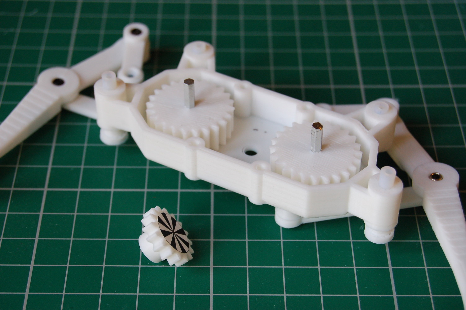
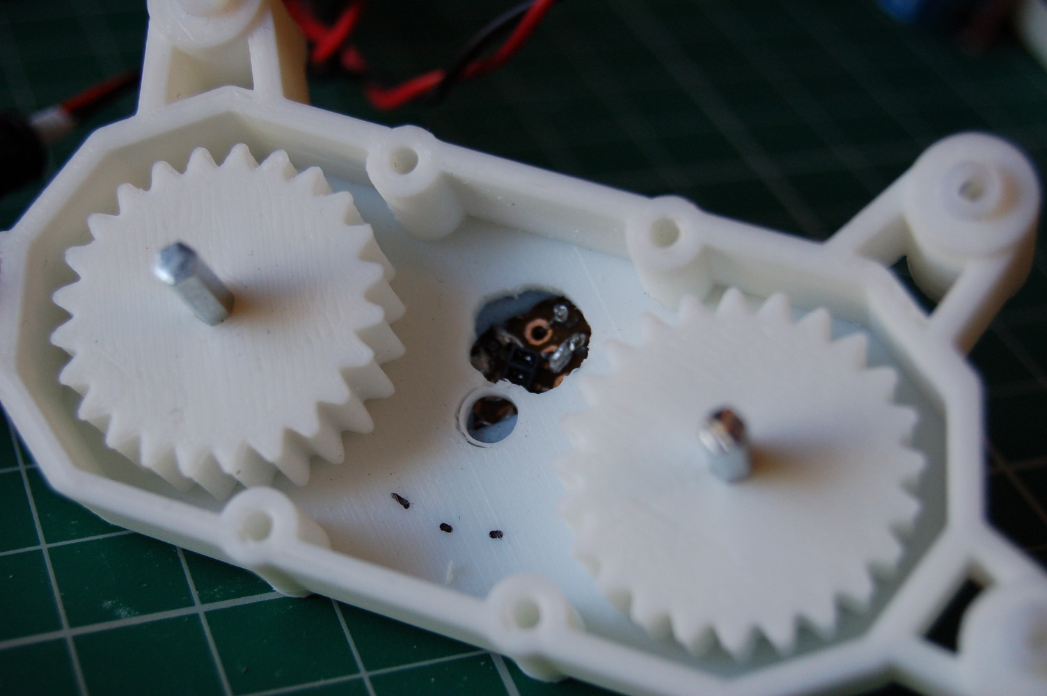
We are using a reflective infrared sensor (ITR8307) that is looking at an encoder disc with black and white stripes, inside the gearbox. The encoder disc is just a piece of paper glued to the center gear driven by the motor. An improvised hole provides a window for the sensor to peek inside. If we measure how long it takes for one stripe to pass in front of the sensor, we can calculate speed (RPM). Knowing the actual speed can enable better control of the motors and also to implement dead reckoning. We are only detecting speed, without direction, to keep things simple. (We want to avoid sudden changes in direction anyway, and the motors are not that fast, so assuming we’re always going the correct way may be safe.)
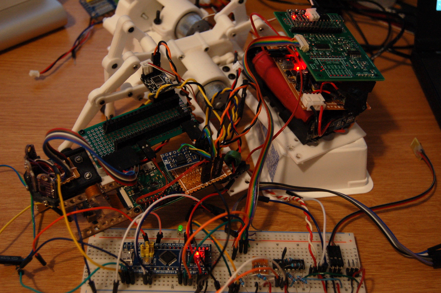
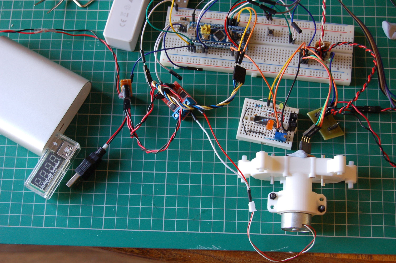
The initial testing on a breadboard looked promising. (Who said that a breadboard makes it quick and easy to connecting things?! It’s a mess!)
But it became obvious that the raw input from the sensor is very noisy and that the sensor needs to be very close to the surface of the disc to get reliable results. The main reason for this is that we’re treating the signal as digital input and want to only see either black or white – but the sensor doesn’t quite work like that: the voltage for a “high” signal obviously depends on the amount of light reflected, which is affected by the distance.
One solution might be to read the voltage as an analog value and do thresholding in software. This method is probably more useful for things like line followers. What we would prefer is a hardware solution that turns the noisy analog singal into a clean digital one, which can easily be read by a microcontroller with an external interrupt.
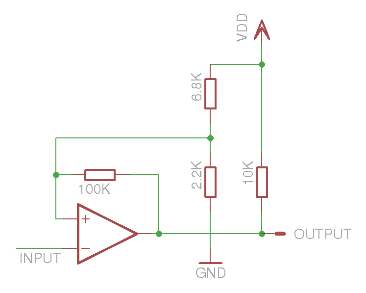
Some more research and experimenting resulted in a circuit which uses a comparator (LM339) with feedback. This produces a nice “black and white” digital output. A very good explanation of the basics can be found in this blog.
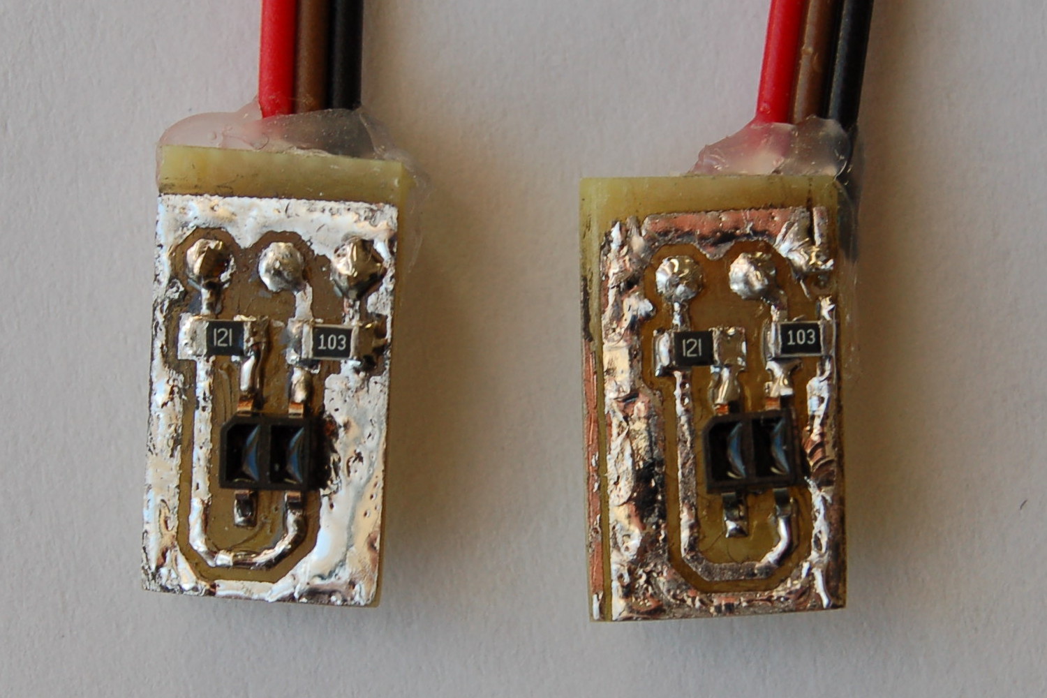
Putting this circuit aside for now, let’s have a look at how the “final” version of the sensors look like:
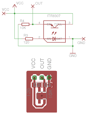
The sensors are mounted on small PCBs with a couple of resistors. The M.E.T. lab has a sophisticated process to make these, using the well-known DIY toner-transfer and vinegar-based etching methods:
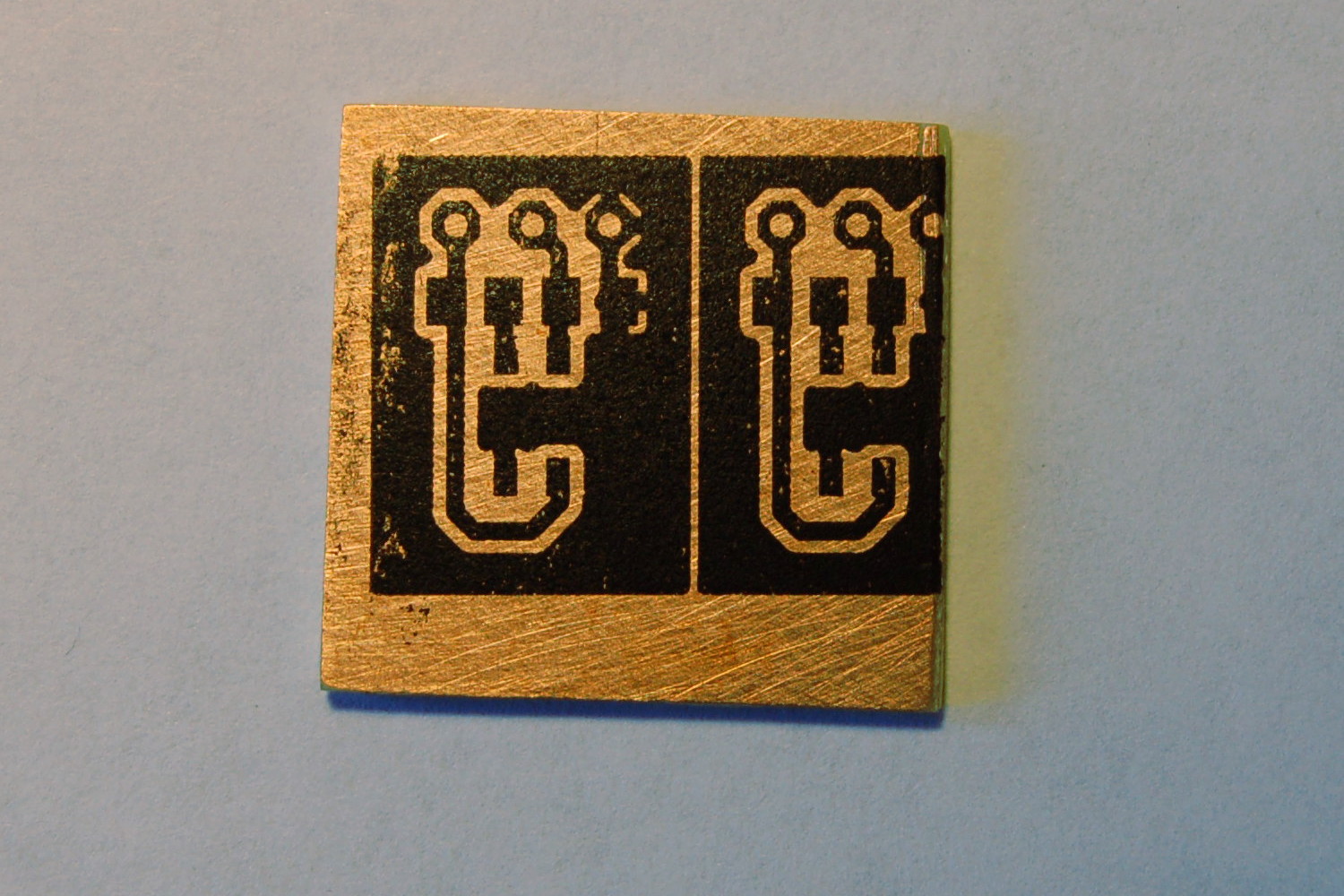
- Print the traces (mirrored) with a laser printer on a backing sheet for self-adhesive labels.
- With a hot iron, transfer this image to the copper surface of the PCB (temperature and pressure is precisely controlled: just press it hard and remove it before things start to burn).
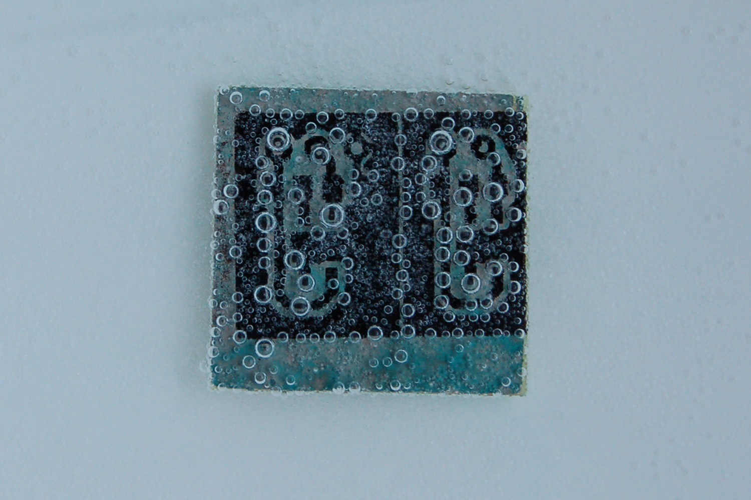
- Pour some water into a small plastic container and add some acetic acid, rocket fuel (hydrogen peroxide) and table salt (using a very exact and secret ratio).
- Watch it bubbling and add more salt as needed.
- Take it out before all the copper disappears.
This process is not always entirely reliable, but this time we were lucky and got a very nice result. (It looks a bit messy on the third image, but this is only because of the uneven surface of the manually tinned traces and the less than ideal lighting. The copper traces are actually perfect.)
Controlling Motor Power
To control motor power, we need two things: something to generate a PWM signal and a motor driver that uses that signal to switch the higher current/voltage for the motors.
The Pi can generate PWM so we could use that directly, but we are using a microcontroller for all the low-level real-time tasks. The PWM output will also depend on the continuous speed measurements, which are especially time-critical, so it makes sense to do both on a microcontroller, leaving only the high-level, non-real time control logic to the Pi.
Last year we had to control four DC motors and five servos, and used an ATmega328 microcontroller, so the number of pins and available PWM outputs were a bit limited. This is why we added another component, a PCA9685 breakout board (a dedicated I2C 16-channel PWM controller). For motor drivers, we used two DRV8833 2-channel motor driver boards. The assembly of all these was the ACF-MAS (Actuator Controller For Motors And Servos). It worked great, it was really easy to use, but it was all a bit bulky.
This year we only have two DC motors so far: these can be controlled by only two PWM channels, so this doesn’t really require a dedicated component. Still, it seems like a good idea to use a proven solution with a lot of room for adding more motors (we have a few secret plans…) – and we always need a bit of over-engineering!
Introducing MOC-SSIU – the MOtor Control and Speed Signal Integrator Unit:
- a PCA9685 I2C 16-channel PWM controller chip
- three 2-channel DRV8833 motor controller boards
- an LM339 comparator to handle speed sensor signals
- connectors for up to six DC motors (and their corresponding sensors)
- a connector to the microcontroller for I2C and sensor output (a 1.25mm pitch JST SMD connector that looks much better than the usual big pin headers and Dupont connectors)
- power connector pins at the bottom (this will sit on top of P-CAMS-2, the power board)
- some “spare” connectors and extra pins for any future ad-hoc extensions, just in case
- all this on a shiny new “professional” PCB!
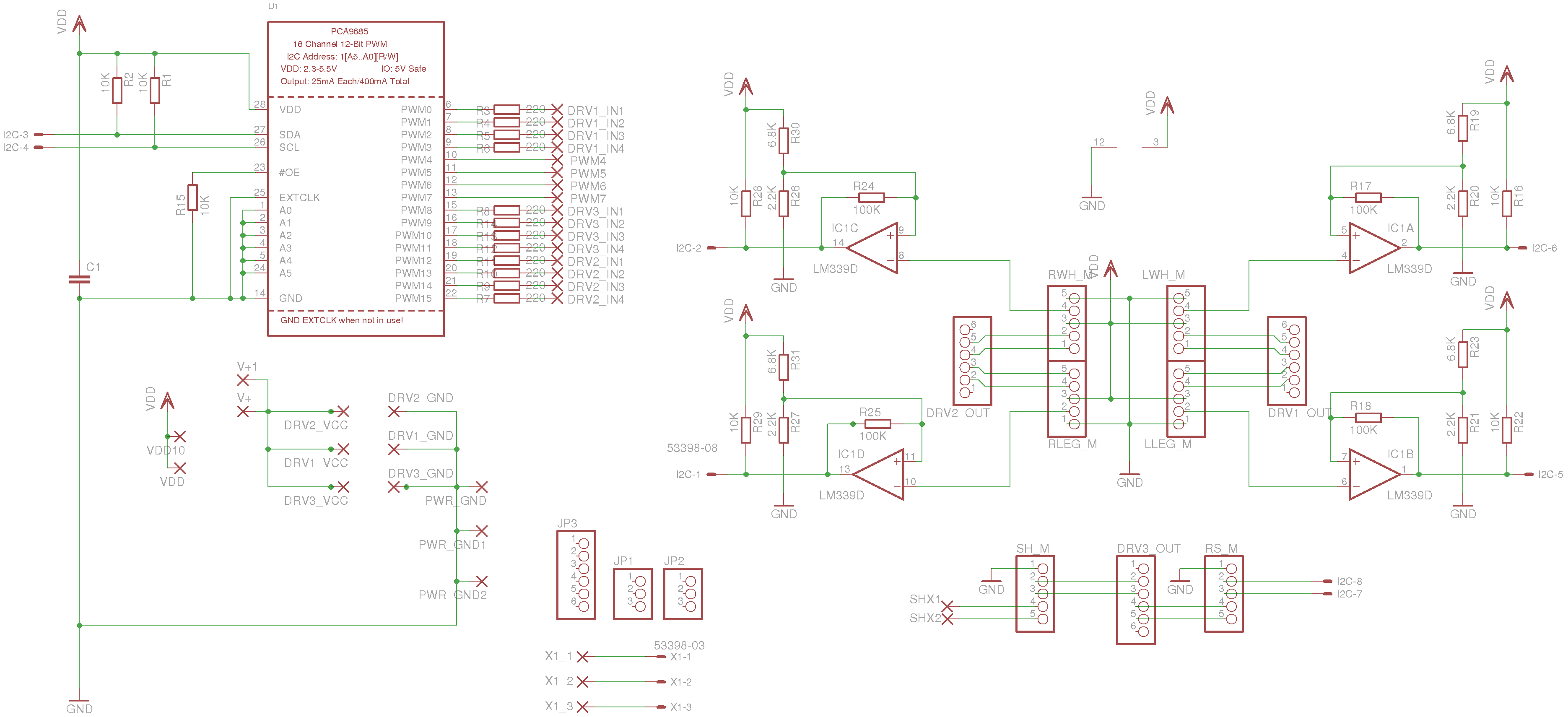
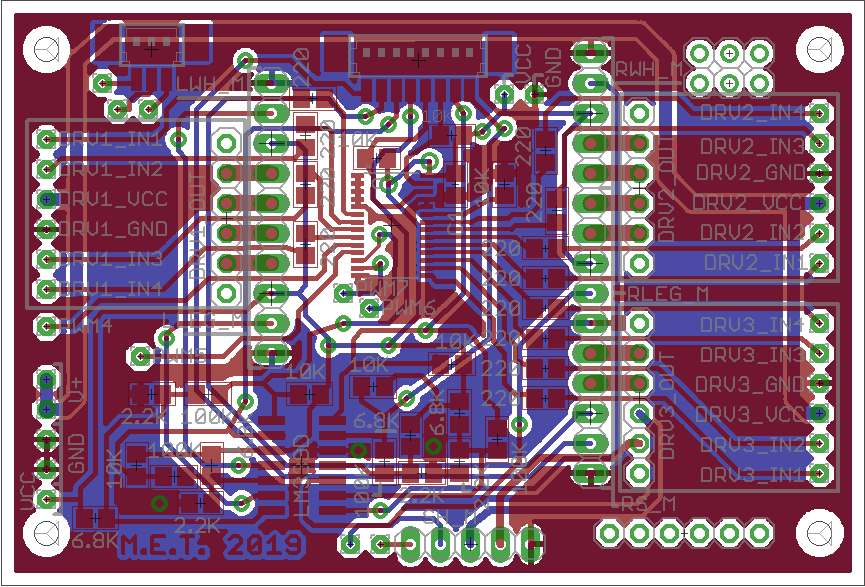
The Eagle files for this – and also for the IR sensor boards – can be found in our GitLab repo.
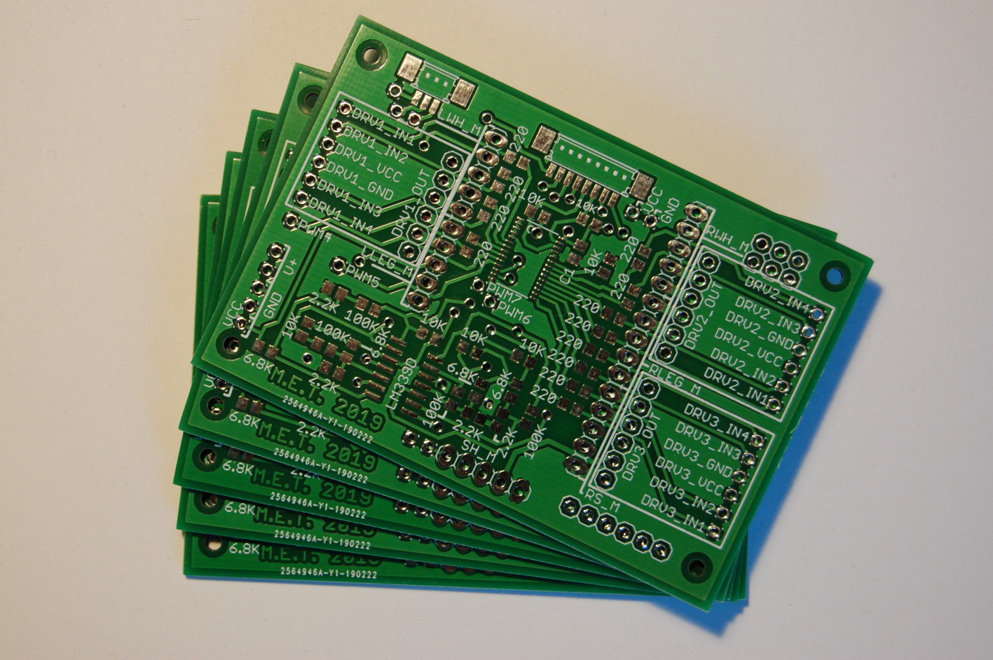
We didn’t trust our own PCB-making process with this, so we ordered the boards (minimum order is five, so we have plenty of spares…) from JLCPCB – and they turned out perfect!
Soldering the SMD components wasn’t too hard, although that PCA9685 chip is tiny! But solder paste (or surface tension?) is magical!

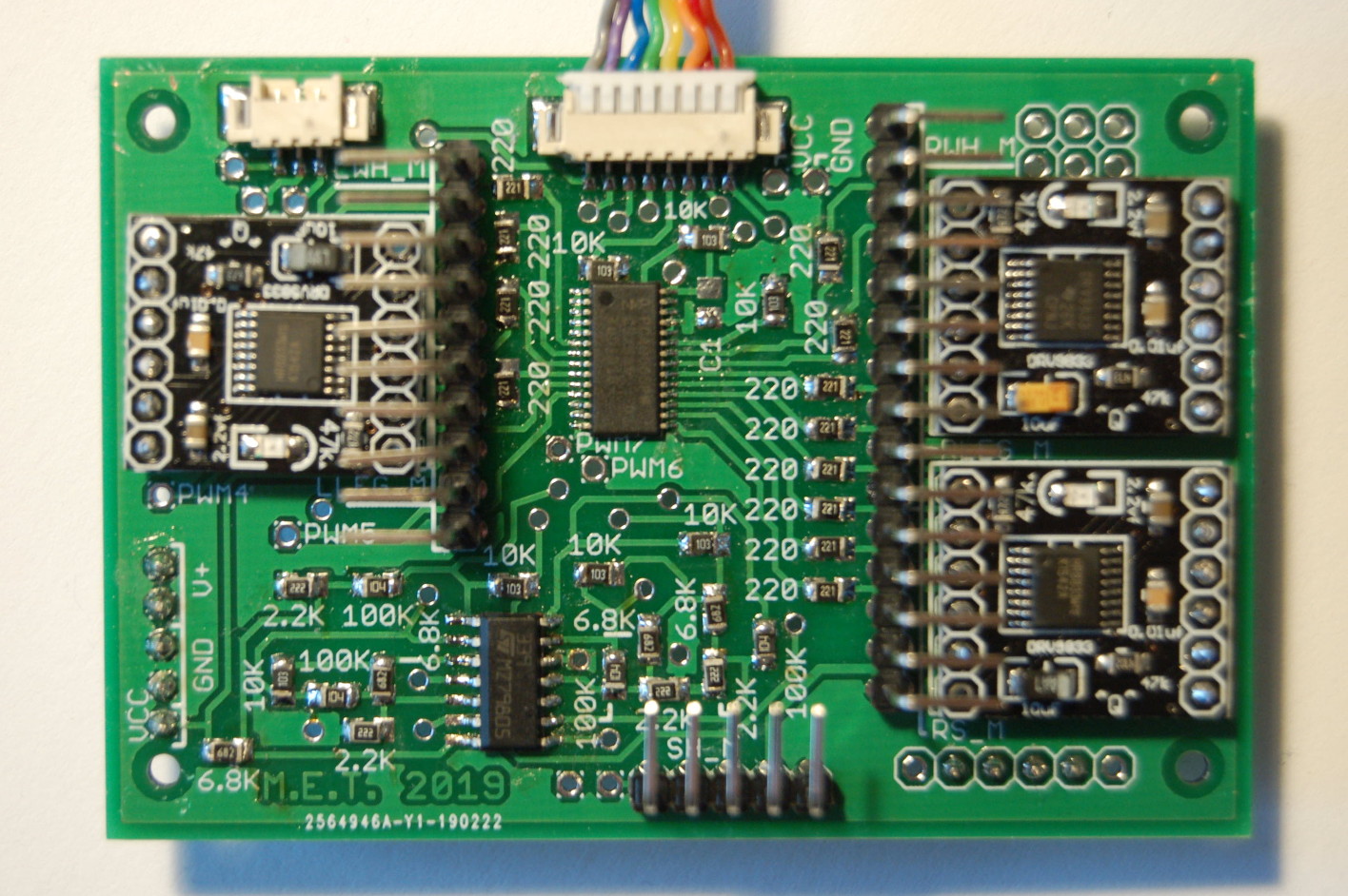
After populating one half of the new board, here is how the first test looked like. Unfortunately this meant disassembling almost everything. The “main” board also needs some rewiring to be able to connect it, we need to find a way to properly attach the sensors (probably printing a new cover for the gearboxes), and most importantly, the code on the microcontroller needs to be updated to actually implement speed control! But more on all this in another post…