
Power
PM-2 and P-CAMS-2
In our previous robot, in the 2018 Pi Wars, we used separate batteries for the electronics (one 18650 with a boost converter) and the motors (two 18650s in series with a buck converter). This was an easy and reliable solution to avoid any interference from electrical noise generated by DC motors. But it’s not very efficient: the batteries will not discharge at the same rate – and just two would probably provide enough total capacity anyway. This time we want to reduce the weight and also save some space. So here are the second versions of our modules:
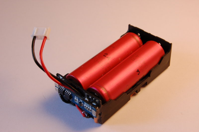
PM-2 (Power Module 2) is essentially a battery holder for two 18650 batteries in series with a protection circuit.
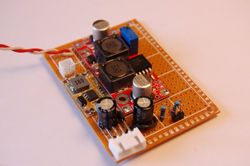
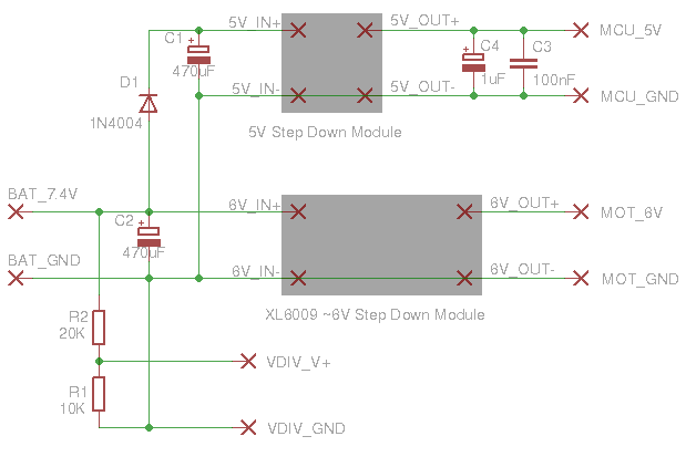
P-CAMS-2 (Power Conversion And Management System 2) consists of two DC converters: one to provide 5V for the electronics, and another to give 6V to DC motors and servos. It also has a voltage divider to provide a usable input for battery voltage monitoring. The circuit is very simple:
Motor Noise!
After making a prototype of P-CAMS-2 on a perfboard, a quick test showed that everything worked fine: Pi Zero running, motors moving. For PWM, we’re using a PCA9685 I2C module: this can control up to 16 motors or servos. It can only use a single frequency, so we’re using 60Hz, as the servos can’t really use something much higher, but this has worked well enough for the DC motors too.
Turning the motors full on and off, driving forwards and backwards was OK. But when we tried varying the speed, I2C suddenly started to fail: I/O errors after a few seconds, all the time. We did have 100n capacitors across the motor terminals, and also bigger electrolytics before each DC converter as buffers, but this was clearly not enough!
Apollo 11 could land on the Moon, despite a hardware problem that caused some scary 1201 and 1202 alarms. But instead of crashing, the software recovered, letting the humans ignore the errors and just carry on!
So there is nothing to worry about, we can fix this in software, like this:
while True:
    try:
        # ...Read inputs etc., then drive: set pwm via I2C...
    except OSError:
        # Don't panic, it's only an error...
        # Just ignore and continue, but keep a count so that we can display this
        # on some fancy control panel later or maybe even plot a chart...
        err_count = err_count + 1
But maybe there is a better solution… Getting lots of errors in a reproducible way now is actually a great opportunity! It means we can investigate the cause, try to change things one by one and see what has an effect on the errors! Much better than having a potential problem lurking somewhere undetected, only to come up later, randomly and unexpectedly!
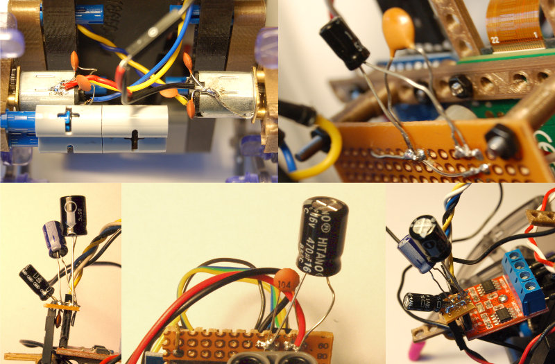
We experimented with adding capacitors to try and filter out the noise: many variations with different values, caps before or after the DC converters, and/or caps closer to the electronics, more caps near the motor driver, caps on the motor terminals, connected to the motor casing, with or without grounding the casing, etc. And we tested each combination, running the motors on low speed for a few minutes and checking the I2C error rate. Some combinations looked promising at first, but none of them provided any major improvement or pointed towards the right direction.
At the end it looked a bit ridiculous…
We’ve done some research and found quite a lot of useful information:
- EE StackExchange: Reduction of DC motor noise
- Pololu: Dealing with Motor Noise
- Andy’s Workshop: Filtering the 5V USB power supply line
Finally, thanks to a brilliant suggestion from Brian, we had a winning solution:
Ferrite bead on the power leads to the electronics, right before the connection to the Pi!
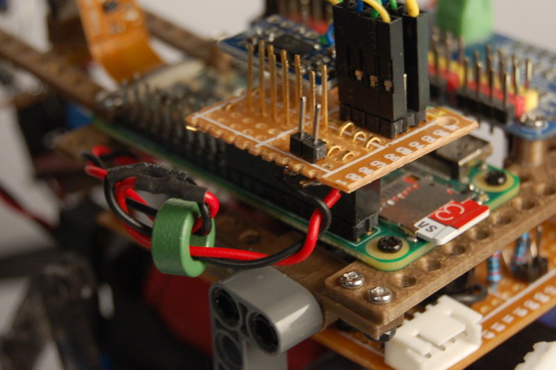
Other combinations (adding the ferrite bead before the DC converter or putting it further away from the connection) didn’t help or only slightly reduced the error rate. So it appears the positioning is very important, even with relatively short wires.
After this small step towards better and cleaner power, we hope we can work on something more creative and less frustrating next time!