
New Motors, New Legs, New Everything!
Here is the next stage in the evolution of our alien robot:
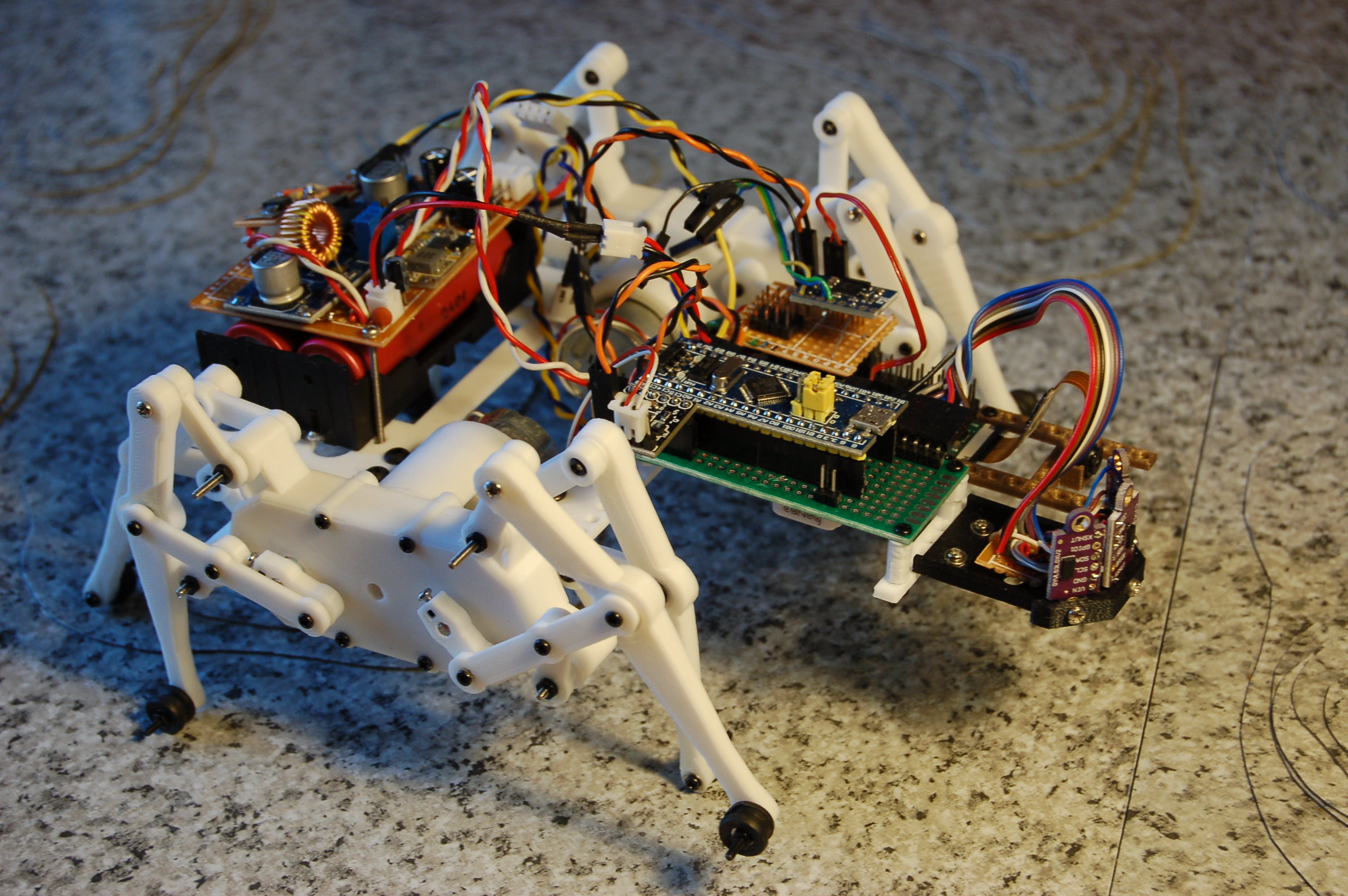
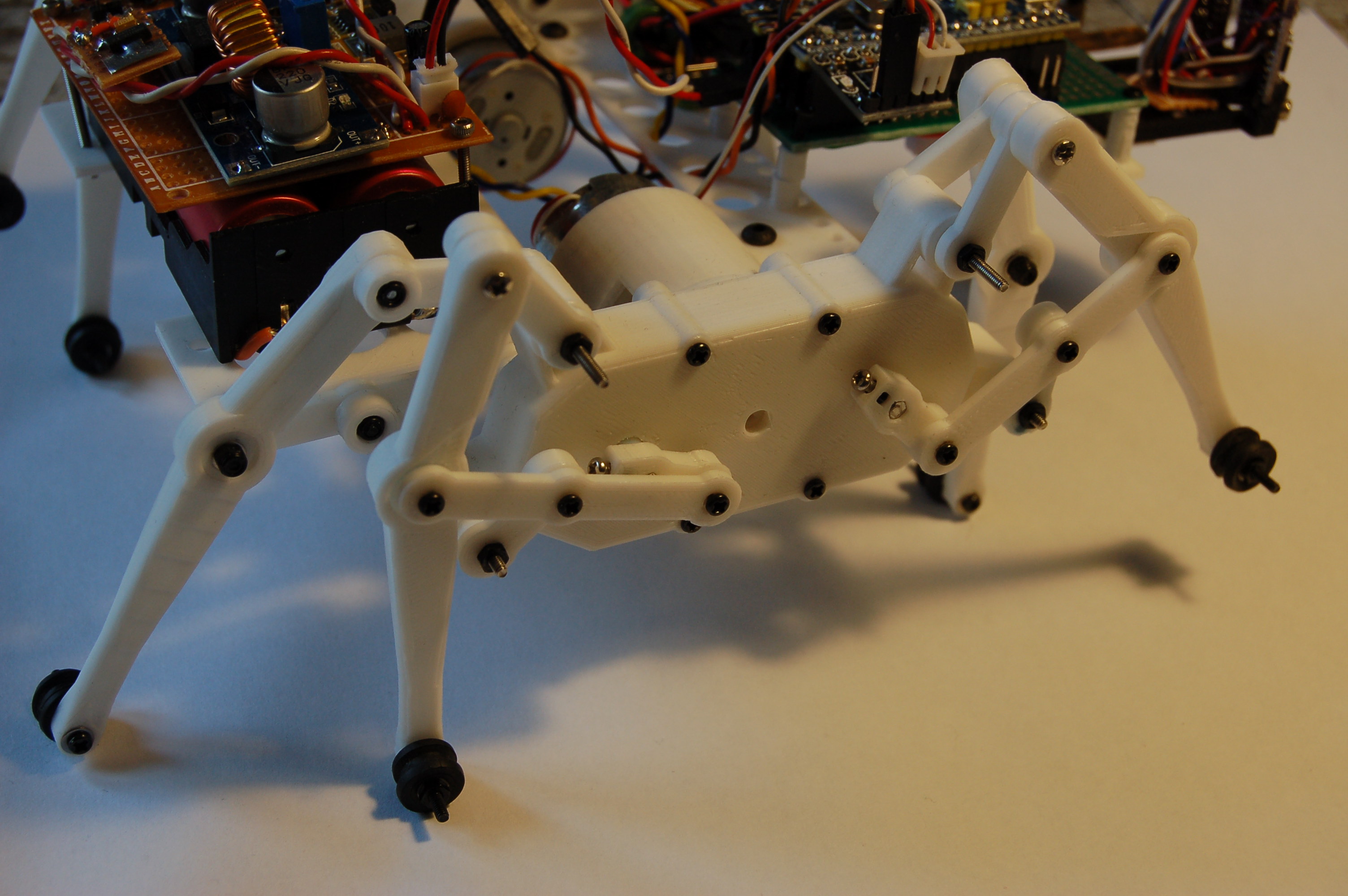
New legs and gearboxes
After an unreasonably long time spent on the design and a lot of experimentation on linkages, we’ve finally made our own leg mechanism. It uses the Klann linkage. Observing how our original toy kit based prototype worked (uses the same mechanism) and especially the resources on the DIY Walkers website were an enormous help.
A byproduct of all this work is “morescad”, a collection of some OpenSCAD utilities, including a module to help making linkages like this.
The total number of parts for the two gearboxes and the eight legs:
- 50 individual 3D-printed parts
- 58 screws
- 2 axle sleeves (to connect the motor to the center gear)
- 4 hexagonal axles (for the two crank gears)
- 4 ball bearings
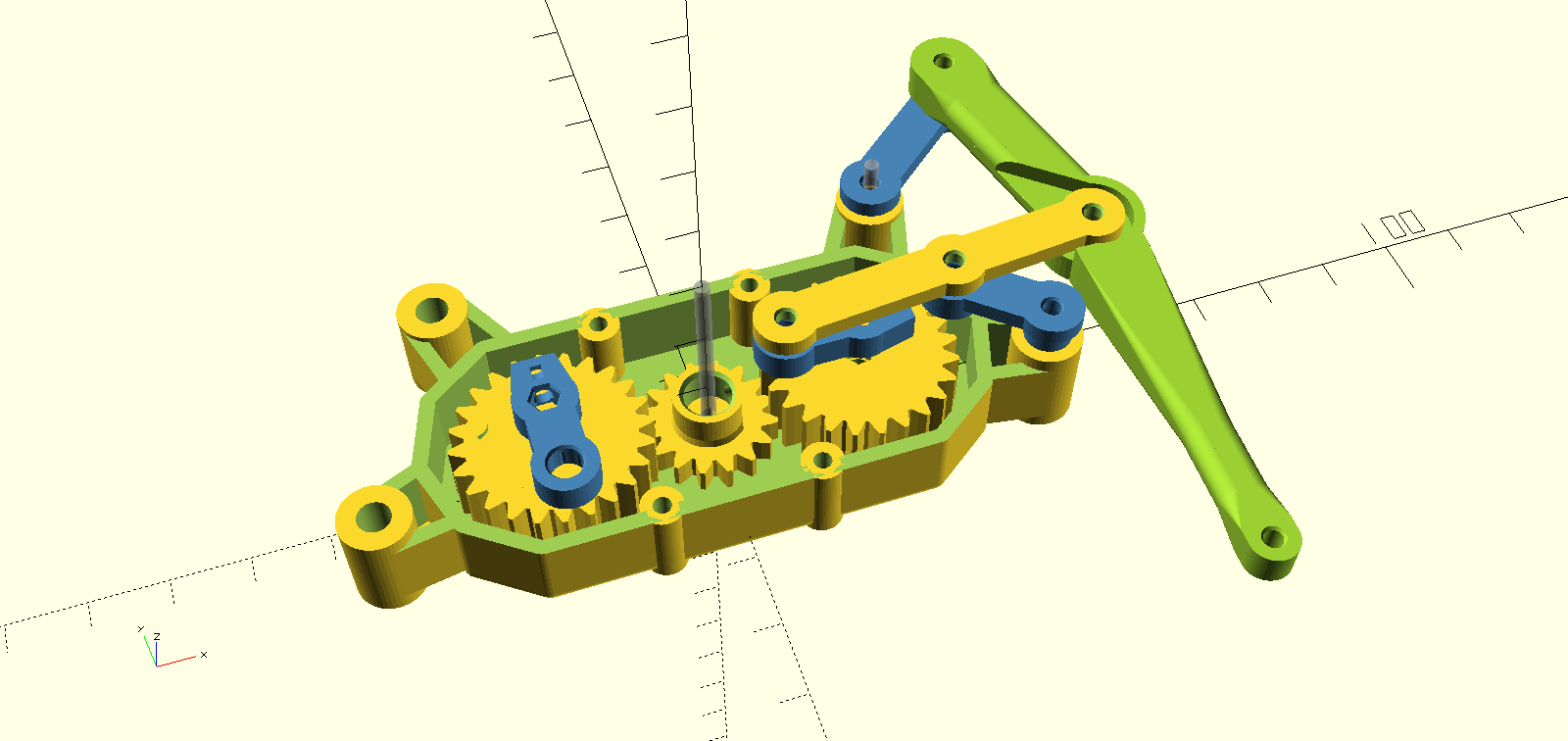
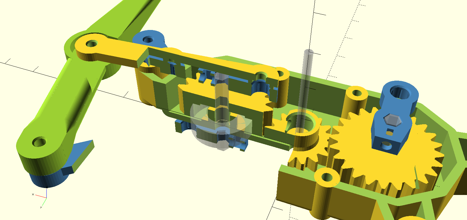
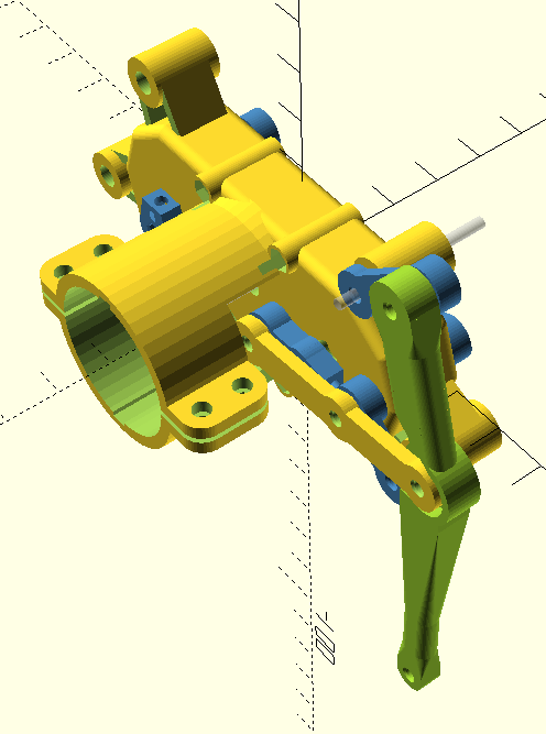
The joints have press-fit self locking nuts and M2 screws, covered with small PTFE tubes (the kind used for 3D printer extruders) to reduce friction. The crank joints (blue bits above/below the gears on the picture) have a hole to insert a nut to hold a set screw connecting to the hexagonal shaft. We also use Loctite threadlocker glue on some of the screws – thanks to Brian C. for the suggestion! (We hope this will prevent us from losing legs like we did with wheels last year due to connections becoming loose.) The two crank gears are connected to the bottom part of the gearbox with ball bearings (transparent gray disc on the picture).
The feet are not finished yet: we need to find something better than the rubber grommets added temporarily for now.
Motors
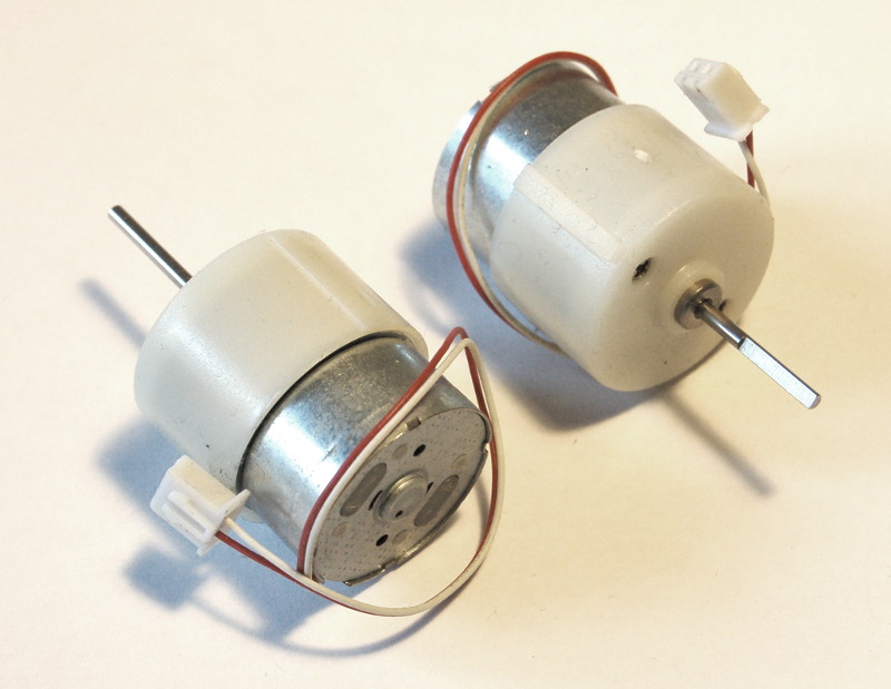
The new motors are 6V “600RPM Mini Metal Gearbox” motors from Ebay, hopefully with a good balance between speed and torque. They are much bigger than the N20 “Micro Metal Gearbox” ones we used earlier and last year. They are not very powerful, but the aim is to keep everything as small and light as possible. The stall current we measured was about 1.5A, and moving the legs freely takes about 2-300mA, so hopefully the tiny DRV8833 motor driver board (same as we used last year) will be able to handle this.
P-CAMS-2 Rev. 2
P-CAMS-2 (Power Conversion And Management System 2) has also been updated: the previous version used a XL6009 buck-boost module, but some testing with the new motors has shown that it’s performance is not quite like as advertised: its max. input current is supposed to be 3A, but set to 6V output with ~8V input, it shuts down immediately if the load reaches 1A at the output. This could be due to some obviously missing components on the board…
So this has now been replaced by an XL4015 buck converter module, that’s slightly more reliable: when stalling a motor and reaching 1.5A (wires getting hot), its output drops to about 5V but it doesn’t shut down. This should be good enough…
Another update is the addition of an AMS1117 3.3V LDO – so that we won’t need to use the Pi’s or the microcontroller’s built-in 3.3V regulator to power all the sensors and additional electronics.
New motor/sensor control board
This is another new part: a microcontroller board to control the motors and read the distance sensors. Previously we used a PCA9685 board to generate PWM, but this new board will probably replace that and will take care of controlling all DC motors and servos and will also handle the distance sensors. The board is a “Blue Pill” with an STM32F103C8 microcontroller – but more on all this later, in another post!
Frame and sensors
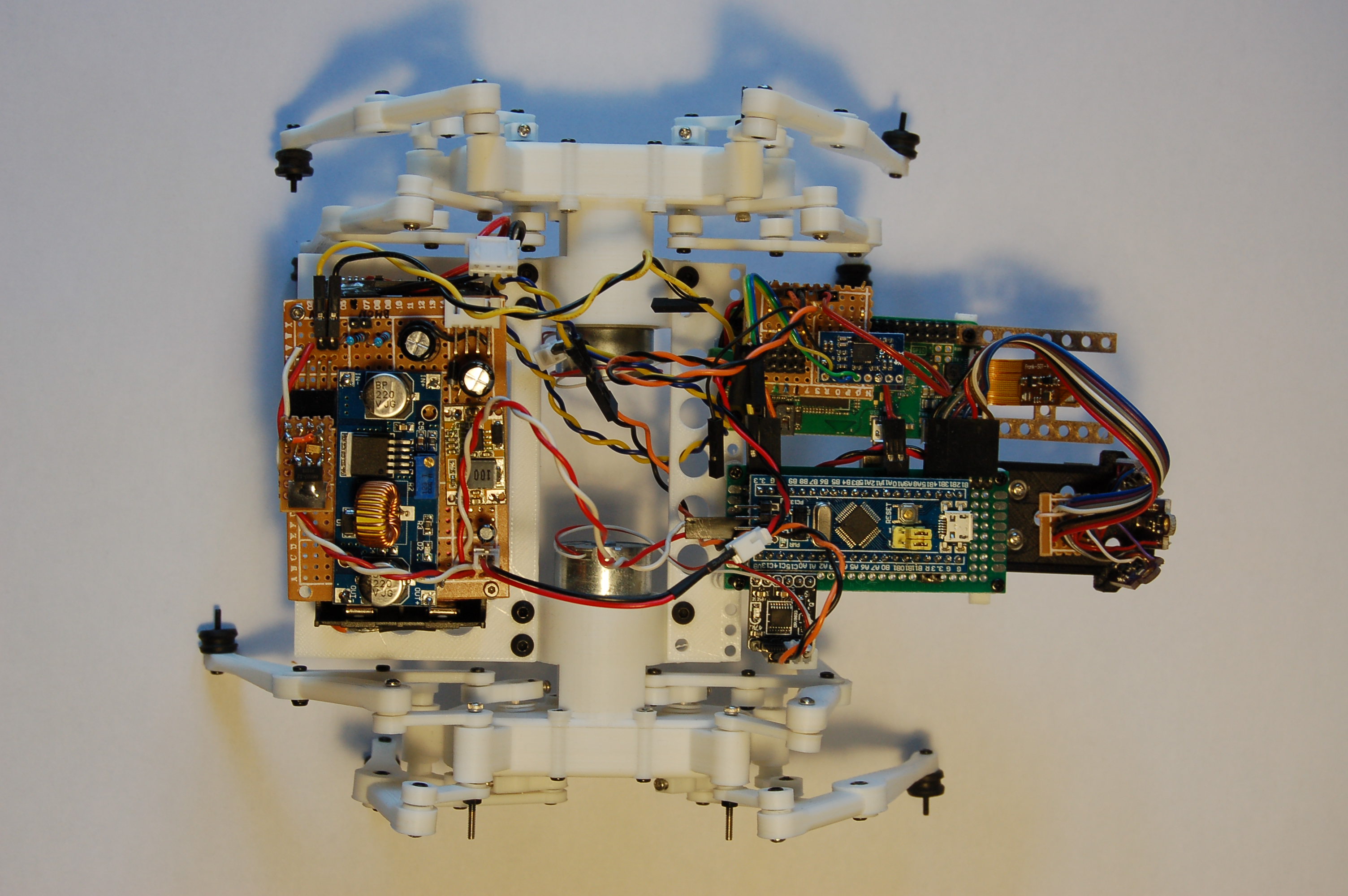
So far we don’t have a complete body for the robot, only a very simple frame to hold the two gearboxes together and to support the various PCBs. This new frame and temporary layout should be enough to test all the components, both the existing ones and some new we’re planning to add later, and to refine movement and control. The ToF distance sensor array at the front is “borrowed” from our previous robot.
But can it walk…? Or run…? Find out in the next post!