
Remote Control
Finally, an update with some walking, running and spinning! We have a long way to go, but at least we have basic remote control working.
From Joystick to Motors
Our robot uses a very alien mechanism to move but it has simple differential steering: one motor on each side drives the legs forwards or backwards, so the robot turns by applying more or less torque on one side – and it can also turn in place by running the motors in opposite directions. This should be straightforward to control with a game controller joystick. But how does this actually work?
We don’t have encoders in the motors yet, so we can’t measure and control speed, all we can do for now is simply vary the motor power (PWM). The game controller gives us the position of the joystick as (x,y) coordinates within [–1, 1]. We need to somehow translate this to motor power (let’s say between –10 and 10) to be applied to left and right respectively.
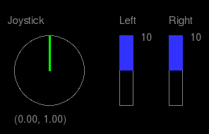
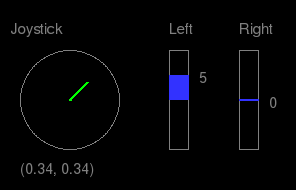
Some examples: driving full speed forwards – and turning right half speed (only the left motor is moving):
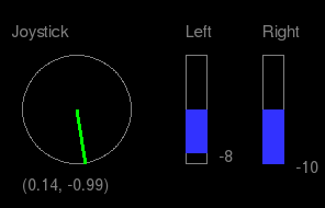
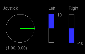
…and going backwards full speed while turning slightly left – and finally, turning right in place, full speed:
There are simple methods to do this directly and to make the joystick control feel “natural”, like this example for the approxeng.input library. However, when the human driver is replaced by a program to drive the robot autonomously, we don’t want to deal with joystick coordinates. It would be much more natural to make the program produce some desired speed and turn direction values instead. So we’ve added this intermediate representation too. Instead of going from joystick to motors directly, we first interpret the joystick input as speed and direction, and then convert that to motor speeds: (x, y) → (speed, direction) → (left, right).
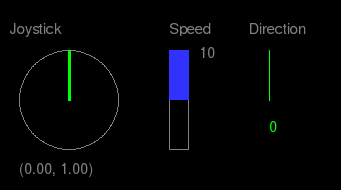
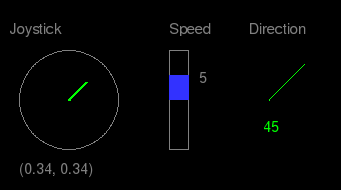
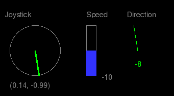
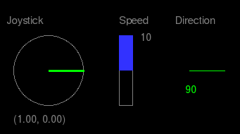
For the first step, we consider (x, y) as a vector, take its length as speed and its angle as turn direction. Pointing upwards is 0°, maximum turn left and right is –90° and 90°. If the vector points down, we negate the speed.
Using the same examples as above, this is what we want:
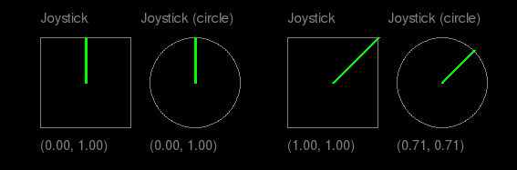
There is one annoying problem with the joystick input however: the joystick actually moves inside a square, not a circle! So moving diagonally we’d get vectors longer than 1 – and different speeds depending on the angle, which is bad. We need to map square coordinates to a circle with this formula:
x → x * sqrt(1.0 - y * y / 2.0)
y → y * sqrt(1.0 - x * x / 2.0)
(For more background and explanation, see this question on Stack Overflow.)
So the next step is to convert the corrected (x,y) from above to (speed,dir) – where speed is in [-10,10] and angle in [-90,90]:
if x == 0 and y == 0:
    return (0, 0)
else:
    (speed, dir) = cart2pol((x, -y))  # cart2pol: convert Cartesian to polar
    dir = np.rad2deg(dir) + 90        # np.rad2deg: convert radians to degrees
    if dir > 90:
        dir = dir - 180
        speed = -speed
    elif dir < -90:
        speed = -speed
    return (int(round(speed * 10)), int(round(dir)))
Finally, to get left and right motor power from (speed, dir): we start by setting the desired speed to both motors, then reduce one side based on the turn angle:
left = float(speed)
right = float(speed)
range = speed * 2.0
diff = (float(dir)/0.9) * (range/100.0)
if dir < 0:
    left = left + diff
else:
    right = right - diff
return (round(left), round(right))
The final result:
The complete code (and some more) for the above calculations can be found here: gitlab.com/marsextraterrestrials/control_logic